


Part of the John Deere Repair Manuals.
All 456 pages of this John Deere 6076 Technical Manual (OEM #CTM42) focus on one engine: the 6076 diesel, as fitted to John Deere CTS Rice Combines. Inside you get a full engine rebuild sequence with disassembly and assembly order, detailed procedures for cylinder head and valves, cylinder block, crankshaft, camshaft and timing gear train, plus complete coverage of the lubrication, cooling, air intake, exhaust, and fuel systems. System diagrams and a full troubleshooting section walk you through diagnosing malfunctions before you pull a single bolt. Head bolt torque runs a four-step sequence: snug cap screw No. 17 to 100 N·m, work through the remaining screws to 100 N·m, retighten the sequence to 125 N·m, then turn each an additional 90–100 degrees. Your machine is down. Get the factory answer on the first try. Bookmarked and searchable; jump to any system or pull up a spec by keyword on any device.
What's Inside This John Deere 6076 Manual
| System | Pages | Key Topics |
|---|---|---|
| Introduction | 2-4 | - |
| Dealer Presentation Sheet | 5 | Engine Application Charts Updated, Engine Coolant Information Revised, Lifting Sling, Lifting Straps, Torque-To-Yield Instructions, Valve Lift Specifications |
| About This Manual | 6-12 | - |
| Safety | 13-20 | Handle Fluids Safely, Prevent Battery Explosions, Avoid High-Pressure Fluids, Wear Protective Clothing, Use Proper Lifting Equipment, Dispose of Waste Properly |
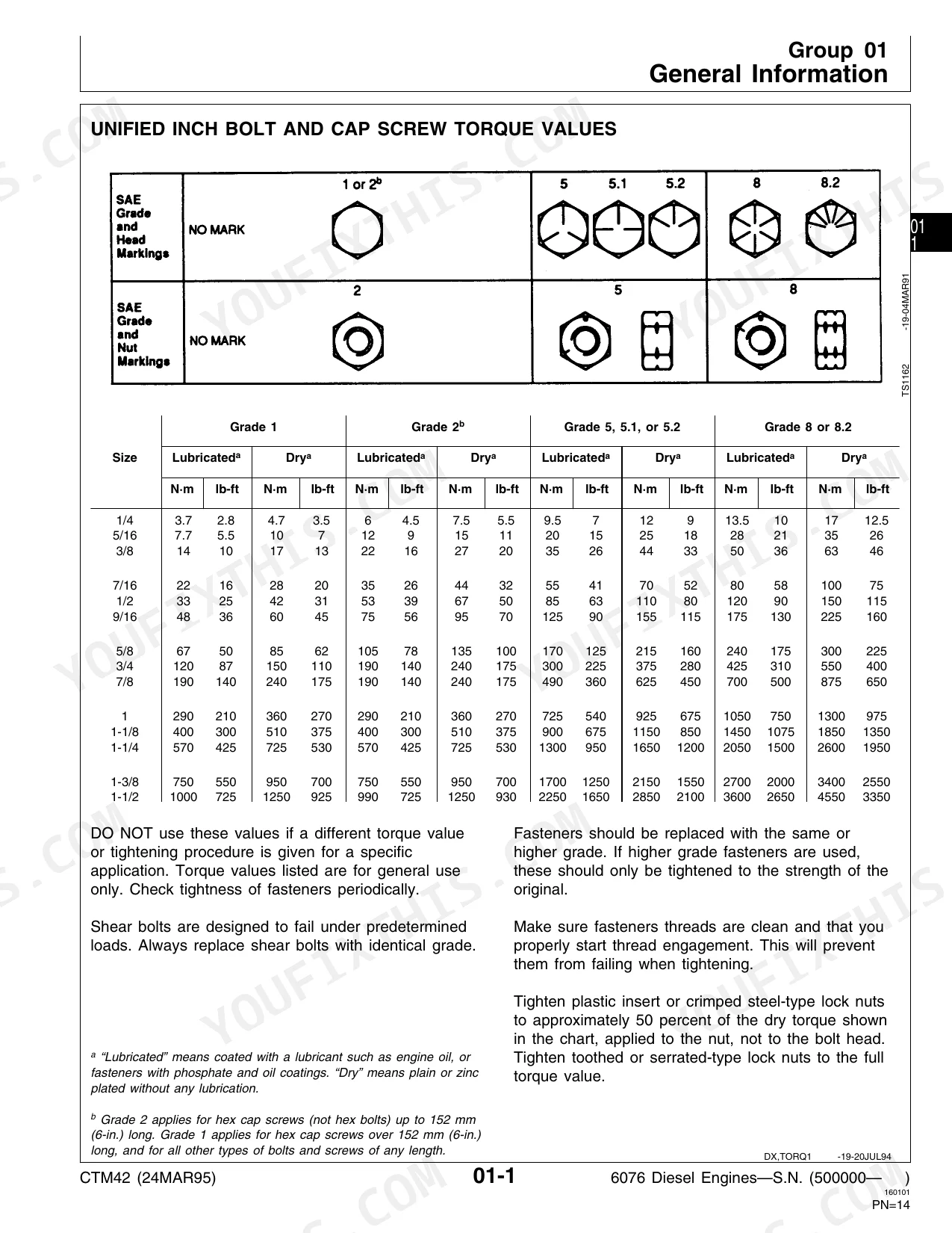
| General Information | 21-26 | Unified Inch Bolt and Cap Screw Torque Values, Metric Bolt and Cap Screw Torque Values, Engine Model Designation, Engine Serial Number Plate Information, Engine Application Chart |
| Fuels, Lubricants, and Coolant | 27-40 | Diesel Fuel, Engine Break-In Oil, Engine Oil, Oilscan and Coolscan, Alternative and Synthetic Lubricants, Recommended Engine Coolant, Engine Coolant Specifications |
| Engine Mounting | 41-46 | Engine Repair Stand, Safety Precautions, Engine Lifting Procedure, Clean Engine, Mount Engine on Repair Stand |
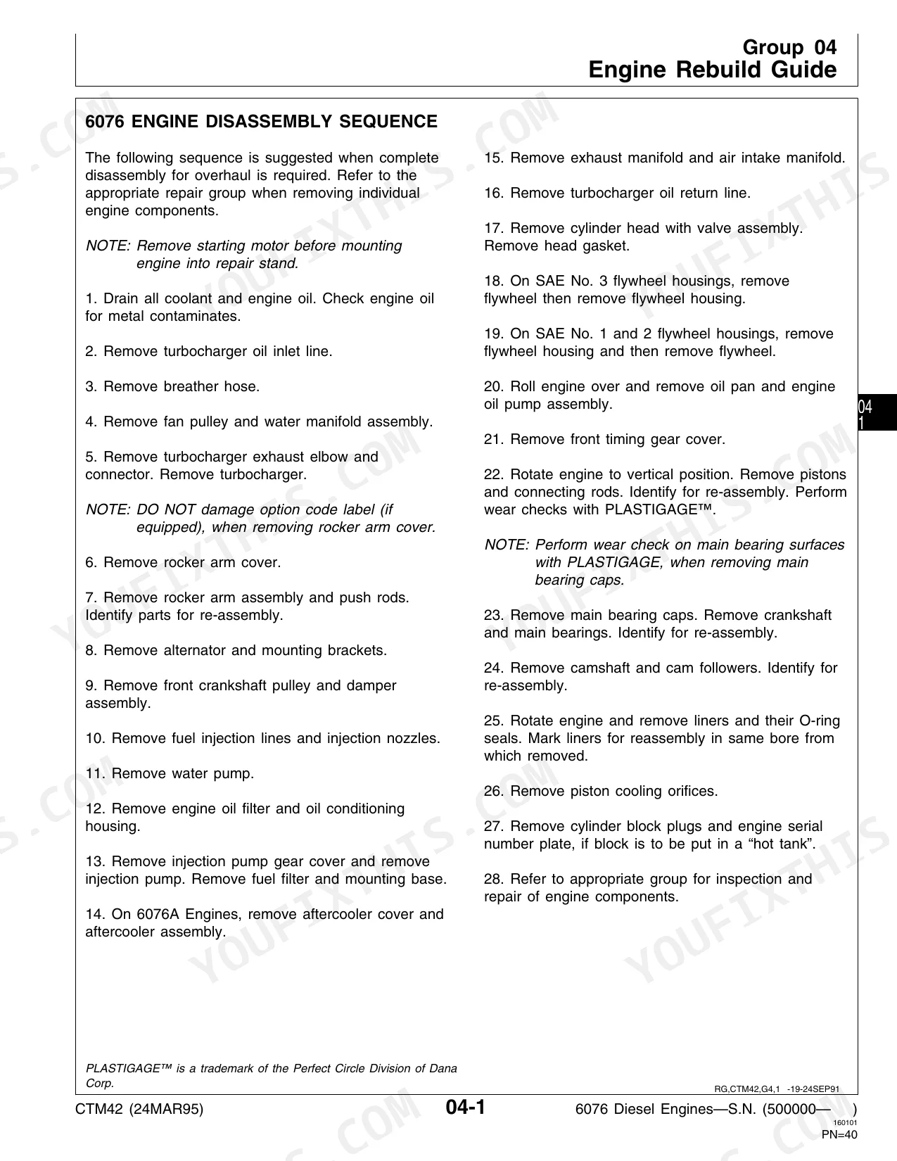
| Engine Rebuild Guide | 47-50 | 6076 Engine Disassembly Sequence, Sealant Application Guidelines, 6076 Engine Assembly Sequence |
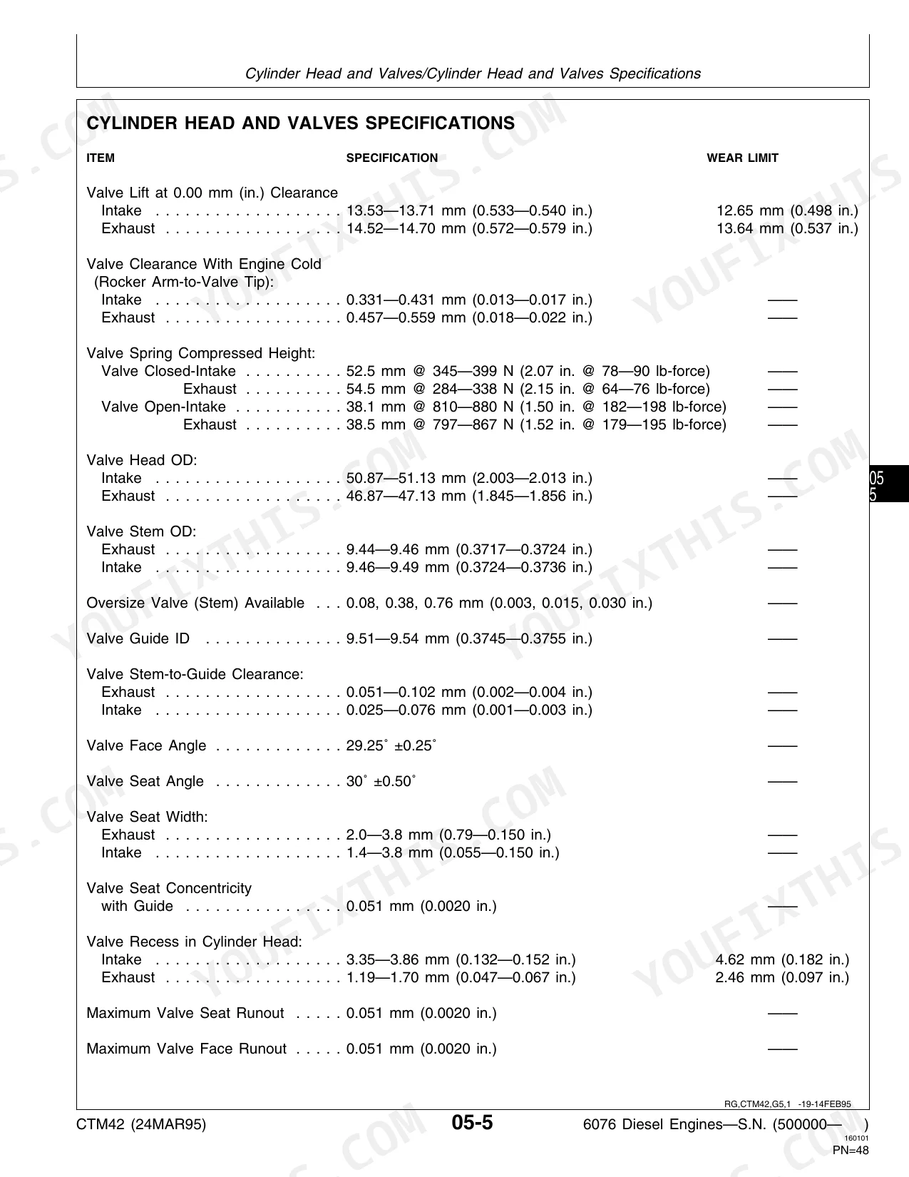
| Cylinder Head and Valves | 51-92 | Special or Essential Tools, Service Equipment and Tools, Other Material, Cylinder Head and Valves Specifications, Check and Adjust Valve Clearance, Check Valve Lift |
| Cylinder Block, Liners, Pistons and Rods | 93-136 | Special or Essential Tools, Service Equipment and Tools, Cylinder Block, Liners, Pistons, And Rods Specifications, Preliminary Liner, Piston |
| Crankshaft, Main Bearings and Flywheel | 137-188 | Special or Essential Tools, Service Equipment and Tools, Other Material, Crankshaft, Main Bearings, And Flywheel Specifications, Failure Analysis |
| Camshaft and Timing Gear Train | 189-210 | Special or Essential Tools, Service Equipment and Tools, Camshaft and Timing Gear Train Specifications, Check Valve Lift, Check Camshaft End Play |
| Lubrication System | 211-226 | Other Material, Drain Engine Oil and Remove Oil Pan, Oil Filter and Oil Conditioning Housing Assembly, Remove Oil Filter and Oil Conditioning Housing, Remove, Inspect |
| Cooling System | 227-252 | Special or Essential Tools, Other Material, Cooling System Specifications, Service Equipment and Tools, Replace Bearings in Standard Duty, Adjustable Fan Drive Assembly |
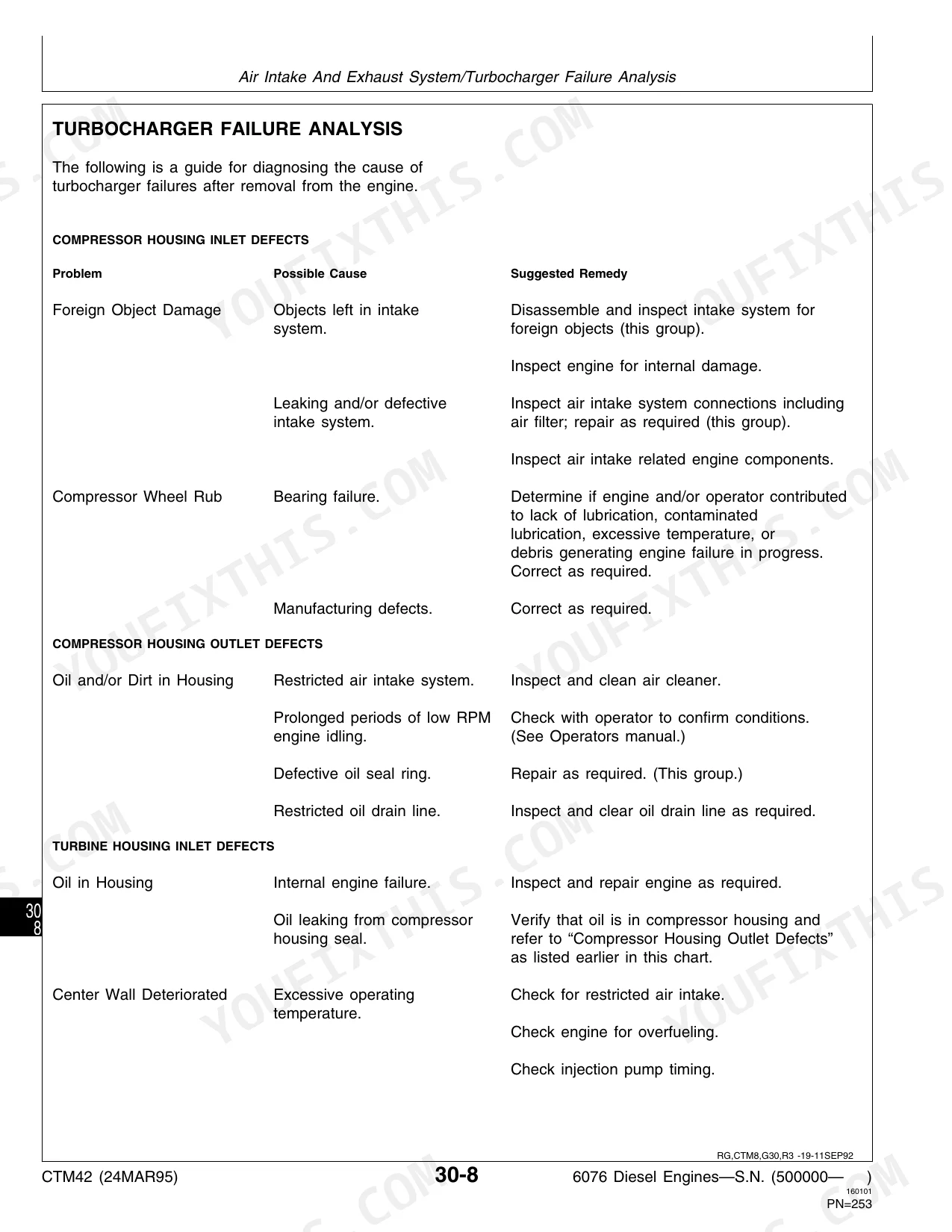
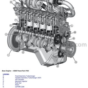
| Air Intake and Exhaust System | 253-284 | Special or Essential Tools, Other Material, Extending Turbocharger Life, Remove Turbocharger, Turbocharger Failure Analysis, Turbocharger Seven-Step Inspection |
| Fuel System | 285-346 | Special or Essential Tools, Other Material, Relieve Fuel System Pressure, Replace Fuel Check Valve, Remove Round Fuel Filter Element, Identification of Fuel Supply Pumps |
| Engine Tune-Up and Break-In | 347-356 | Effects of Altitude and Temperature on Engine Performance, Preliminary Engine Testing, General Tune-Up Recommendations, Dynamometer Test, Engine Break-In Guidelines |
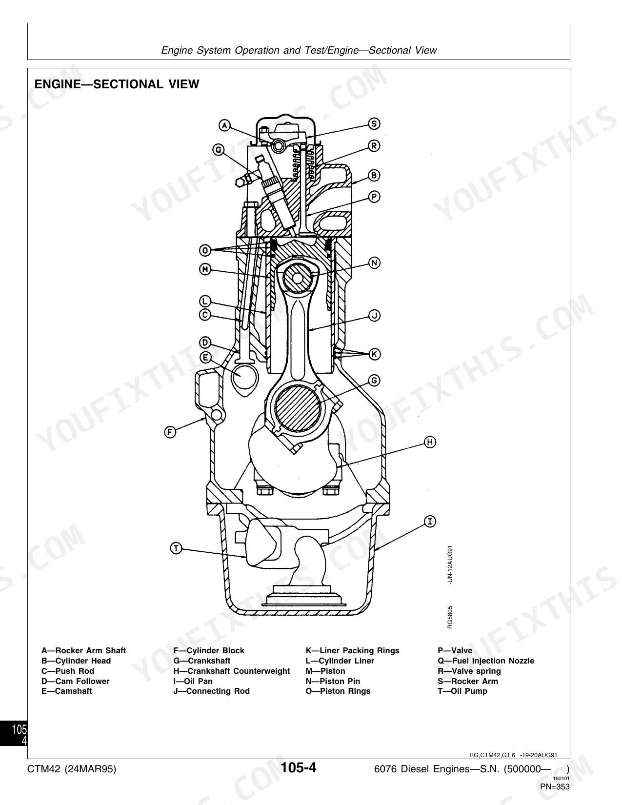
| Engine System Operation and Test | 357-380 | Special or Essential Tools, Engine Test Specifications, Engine, Sectional View, General Engine Description, How the Lubrication System Works, How the Cooling System Works |
| Air Intake System Operation and Test | 381-390 | Special or Essential Tools, Air Intake and Exhaust System Test Specifications, Diagnosing Air Intake Malfunctions, How the Air Intake and Exhaust System Works |
| Fuel System Operation and Test | 391-442 | Special or Essential Tools, Fuel System Test Specifications, Fuel System Operation, In-Line Fuel Injection Pump, Rotary Fuel Injection Pump |
| Dealer Fabricated Tools | 443-444 | How to Make Tools |
Quick Reference Specifications
| Specification | Value | Page |
|---|---|---|
| Cylinder Head-to-Cylinder Block Torque (Grade 180 Flanged-Head Cap Screws) | 1. Tighten cap screw No. 17 to 100 N·m (75 lb-ft). 2. Tighten all remaining cap screws to 100 N·m (75 lb-ft), beginning with No. 1 and proceed sequentially. 3. Retighten all cap screws to 125 N·m (95 lb-ft) beginning with No. 1. 4. Turn each cap screw 90˚—100˚. | p. 85 |
| Cylinder Head-to-Cylinder Block Torque (Grade 180 Marked “SPECIAL” Flanged-Head Cap Screws) | 1. Tighten cap screw No. 17 to 80 N·m (60 lb-ft). 2. Sequentially tighten all cap screws to 80 N·m (60 lb-ft). 3. Sequentially turn each cap screw 90˚. 4. Sequentially turn each cap screw 90˚. 5. Sequentially turn each cap screw 90˚ (Total turn from steps 3, 4, 5 is 270˚ ±5˚). | p. 86 |
| Mechanical Fuel Supply Pump Minimum Output Pressure | 200 kPa (2.0 bar) (29.0 psi) | p. 392 |
| Supply Pump Mounting Stud Nuts Torque | 5—7 N·m (4—5 lb-ft)(45—60 lb-in.) | p. 289 |
| Crankshaft Rear Oil Seal-to-Housing Maximum Runout | 0.152 mm (0.0060 in.) | p. 142 |
| Rear Crankshaft Oil Seal Housing Torque | 27 N·m (20 lb-ft) | p. 144 |
| Injection Pump-to-Cylinder Block Stud Nuts Torque | 47 N·m (35 lb-ft) | p. 289 |
| Injection Pump Drive Gear-to-Pump Hub Cap Screws Torque (A-Series Injection Pumps) | 47 N·m (35 lb-ft) | p. 289 |
| Fuel Filter Base-to-Cylinder Block Torque | 34—54 N·m (25—40 lb-ft) | p. 289 |
| Electric Supply Pump Filter Screen Replacement Condition | Replace if screen is damaged, either by holes or sealing surfaces. | p. 304 |
| Water Pump Impeller Bore ID | 15.849—15.875 mm (0.624—0.625 in.) | p. 229 |
| Water Pump Shaft OD Impeller End | 15.905—15.917 mm (0.626—0.627 in.) | p. 229 |
John Deere 6076 Common Problems This Manual Covers
John Deere 6076 making oil and smelling like diesel fuel mixing into the engine crankcase
Inspect the mechanical fuel supply pump on page 408 for a broken spindle or missing springs. Replace the pump immediately if damaged to prevent severe dilution. Torque the new supply pump mounting stud nuts to exactly 5 to 7 N·m (4 to 5 lb-ft) as specified on page 289.
Manual Section: Mechanical Fuel Supply Pump Malfunctions Diagnosis p. 408Engine temperature gauge spiking and overheating under heavy operating loads or during dynamometer testing
Test the cooling system leakage pressure at 50 kPa (7 psi) using the procedure on page 359. Check for a damaged cylinder head gasket or overloaded engine. If the water pump is leaking, replace it and torque the cylinder block cap screws to 27 N·m (20 lb-ft) per page 231.
Manual Section: Engine Malfunctions Diagnosis p. 359Hard starting even when engine is hot accompanied by excessive black cranking smoke from exhaust
Measure the mechanical fuel supply pump output pressure on page 392 to ensure it meets the 200 kPa (29.0 psi) minimum specification. Verify the fuel injection pump timing is set to TDC. Retorque the injection pump drive gear cover cap screws to 27 N·m (20 lb-ft) shown on page 289.
Manual Section: Fuel System Malfunctions Diagnosis p. 392Coolant dripping steadily from the water pump weep hole and mixing with engine oil
Drain the coolant and remove the water pump. Do not reuse the bearing and impeller once removed, per the guidelines on page 242. Install a new overhaul kit and verify the new water pump impeller bore ID measures between 15.849 and 15.875 mm (0.624 and 0.625 in.) as detailed on page 229.
Manual Section: Cooling System p. 242Frequently Asked Questions
What are the torque specifications for John Deere 6076 cylinder head bolts?
For Grade 180 flanged-head cap screws, tighten to 100 N·m (75 lb-ft) initially, then retighten to 125 N·m (95 lb-ft), and finally turn an additional 90˚—100˚. For "SPECIAL" marked flanged-head cap screws, tighten to 80 N·m (60 lb-ft) sequentially, then turn each cap screw 90˚ three times for a total of 270˚ ±5˚. p. 85
How to diagnose error codes on John Deere 6076 engine?
The manual provides symptom-based diagnostic charts for engine malfunctions, rather than specific error codes. For example, if the engine "Will Not Crank," possible problems include electrical system malfunction or a defective starter solenoid, with solutions like checking battery connections or replacing the starter solenoid. p. 374
What are the replacement specifications for the Fuel transfer pump?
The manual indicates that if the mechanical fuel supply pump is defective or not operating normally after component inspection/repair, the entire pump assembly should be replaced. For example, if a broken spindle is found, the solution is to replace the pump. p. 408
What are the replacement specifications for the Rear crank seal?
If the rear oil seal is replaced, the rear wear sleeve must also be replaced as a matched set. The seal and wear sleeve assembly should not be separated; if they become separated, discard and replace with a new assembly. The JDG476(85) Crankshaft Rear Oil Seal Installation Tool Set is required for installation. p. 182
How quickly can I access this manual after buying?
This is a 456-page searchable PDF ready for immediate download. Works on any device, so pull it up on your phone while you're under the hood. No shipping, no waiting.
Am I able to print pages from this manual?
Absolutely. No DRM or copy protection. Print the whole manual or just the pages you need. Any home or office printer works.


Reviews
There are no reviews yet.