


Part of the John Deere Repair Manuals.
This is the John Deere electrical diagnostics service manual (TM4487ELEC) for the early 6100, 6200, 6300 and 6400 tractors, covering machines up to approximately serial number 101000 with the Saran-built 3029, 4039, 4045, 6059 and 6068 engines. Its 149 pages are written for an experienced technician working the electrical system.The manual is built around functional schematics and wiring harness diagrams: system diagrams for the complete tractor, plus engine, cowl, transmission and cab roof harness drawings with component locations and instrument unit plug arrangements. The sub-system diagnostics group provides step-by-step tests for the starting motor and charging circuit, instrument unit and lighting, exterior lights, blower and air conditioning, and the electronic rockshaft control.Use it to trace no-start, charging, lighting, gauge, HVAC and rockshaft faults by circuit, with fuse ratings and pin assignments called out.
What's Inside This John Deere 6100, 6200, 6300, 6400 Manual
| System | Pages | Key Topics |
|---|---|---|
| Foreword | 4 | Introduction, Safety Messages, Manual Structure, Service Information |
| Electrical Wiring Information | 5 | Wiring Variations, Diagnostic Identification Method, Fuse F105 Check |
| Group 10 - System Diagrams (Ece) | 6-13 | Component Designations, Functional Schematics, Wiring Harness Diagrams, Component Locations, Instrument Unit Details |
| Functional Schematic (Complete Tractor) | 14 | Overall Electrical System Layout, Interconnections, Main Power Distribution |
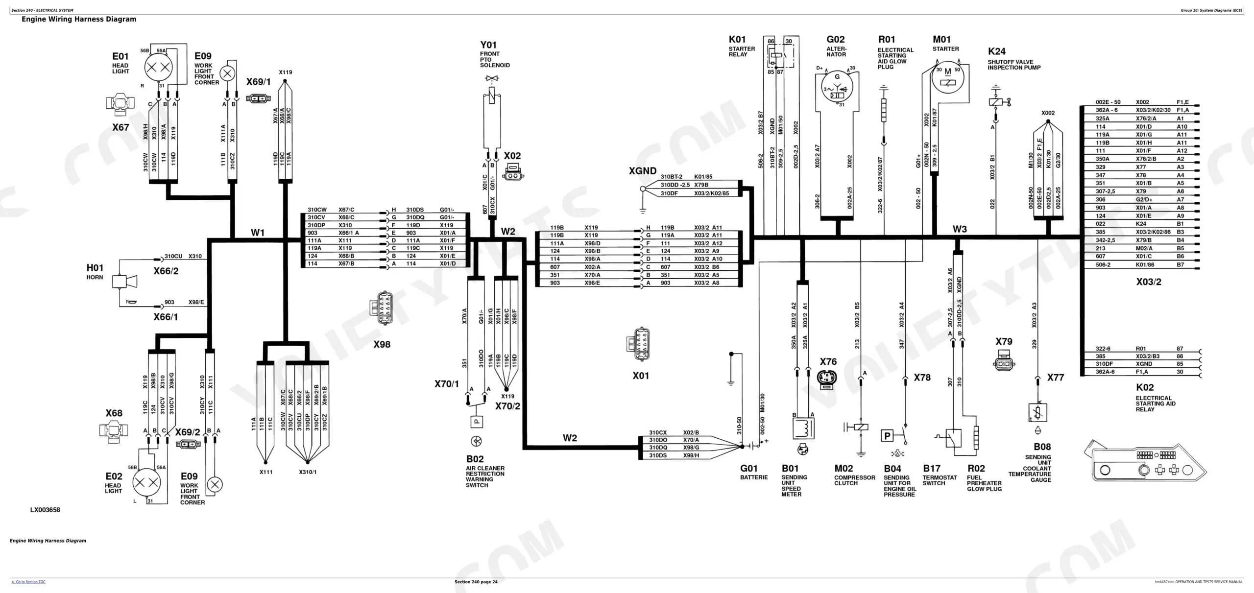
| Engine Wiring Harness Diagram | 31-32 | Engine Electrical Connections, Sensor Locations, Actuator Wiring |
| Cowl Wiring and Harness Diagram | 36-43 | Cowl Area Electrical Routing, Switch Connections, Instrument Panel Wiring |
| Transmission Wiring and Harness Diagram | 46-47 | Transmission Sensors, Solenoids, Control Unit Connections |
| Cab Roof Wiring and Harness Diagram | 50-51 | Cab Lighting, Radio, Wiper Wiring, Roof-Mounted Components |
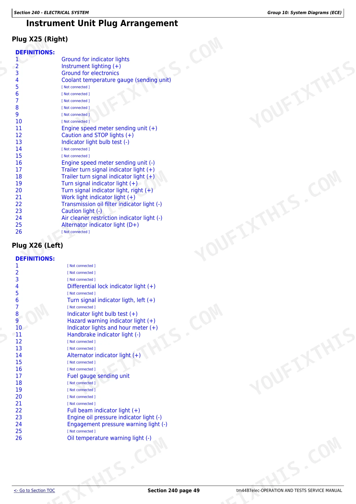
| Instrument Unit Plug Arrangement | 56 | Plug X25 Definitions, Plug X26 Definitions, Pin Assignments |
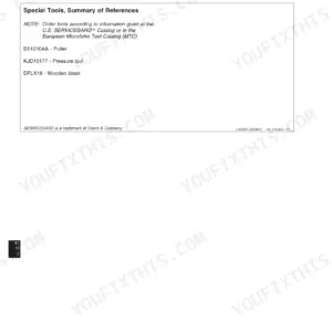
| Group 15 - Sub-System Diagnostics (Ece) | 52-59 | Special Tools, Starting Motor Diagnostics, Instrument Unit Diagnostics, Control Unit Diagnostics, Handbrake Diagnostics, PTO Diagnostics |
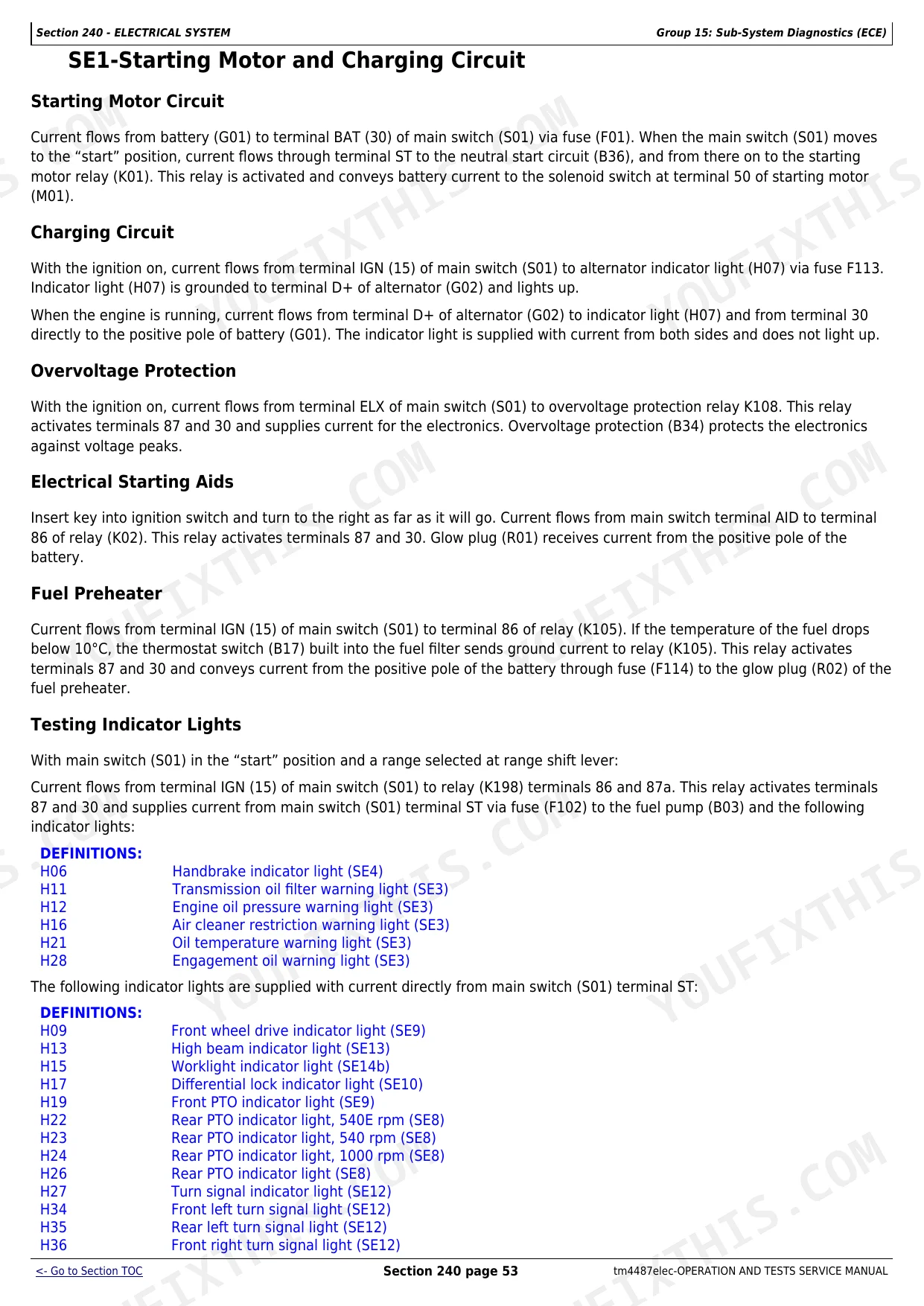
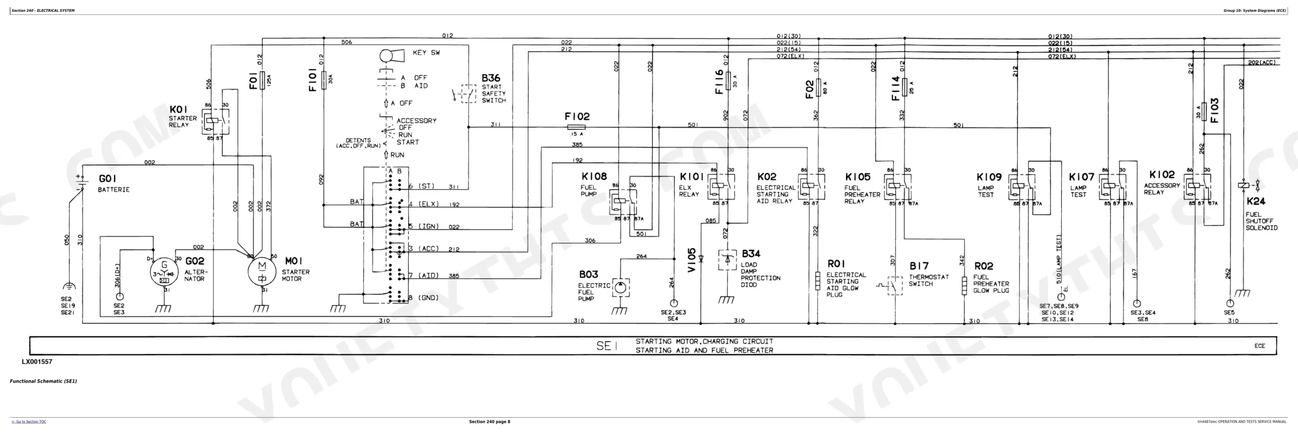
| SE1-Starting Motor and Charging Circuit | 60-61 | Starting Motor Circuit, Charging Circuit, Overvoltage Protection, Electrical Starting Aids, Fuel Preheater, Indicator Lights Testing |
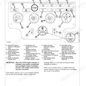
| SE2-Instrument Unit and Lighting | 65 | Instrument Unit Power Flow, Gauge Operation, Sensor Inputs, Tachometer Pulses |
| SE13-Lights | 109-110 | Parking Light Circuit, Low Beam Operation, High Beam Operation, Hazard Warning Flasher, Cab Frame Lights |
| SE17-Blower and Air Conditioning System | 128-129 | Blower Motor Operation, Resistor Stages, Compressor Clutch Control, Thermostat Switch, Pressure Switch |
| SE21-Electronic Rockshaft Control | 144-145 | Control Unit Inputs, Draft Sensors, Position Sensor, Height Potentiometer, Stepper Motor Operation |
Quick Reference Specifications
| Specification | Value | Page |
|---|---|---|
| Fuse F01 Rating | 10 A | p. 15 |
| Fuse F113 Rating | 10 A | p. 15 |
| Fuse F213 Rating | 15 A | p. 27 |
| Fuse F214 Rating | 15 A | p. 27 |
| Fuel Preheater Activation Temperature | 10°C | p. 60 |
| System Voltage (Nominal) | 12V | p. 54 |
| Multimeter Model | JT05791 | p. 59 |
| PTO Speed Meter (540E rpm) | 540E rpm | p. 8 |
| PTO Speed Meter (1000 rpm) | 1000 rpm | p. 8 |
John Deere 6100, 6200, 6300, 6400 Common Problems This Manual Covers
No-start or long cranking
Hard starting and extended cranking on these tractors are diagnosed through the starting and charging circuit. This sub-system section tests the starting motor, charging circuit, overvoltage protection and starting aids.
Manual Section: SE1-Starting Motor and Charging Circuit p. 60Erratic gauges or warning lights
When instrument gauges read wrong or warning lights behave oddly, the fault is usually in the instrument unit power flow or its sensor inputs. This section covers gauge operation and tachometer pulses.
Manual Section: SE2-Instrument Unit and Lighting p. 65Lights or hazard flasher not working
Failed parking, low or high beam, or a dead hazard flasher are traced through the lighting sub-system, which maps each circuit and the cab frame lights.
Manual Section: SE13-Lights p. 109Blower or air conditioning inoperative
A blower that will not run at all speeds, or an A/C compressor that will not engage, points to the blower resistor stages, thermostat switch or pressure switch covered in this section.
Manual Section: SE17-Blower and Air Conditioning System p. 128Electronic rockshaft will not lift
Hitch problems on machines with electronic hitch control come back to the draft and position sensors, height potentiometer or stepper motor documented in the rockshaft control section.
Manual Section: SE21-Electronic Rockshaft Control p. 144Wiring differs from the diagram
These tractors left the factory with wiring variations tied to serial number, so a harness may not match a given diagram. The electrical wiring information explains the variations and the fuse F105 identification method.
Manual Section: Electrical Wiring Information p. 5Frequently Asked Questions
Which tractors does this manual cover?
It covers the early John Deere 6100, 6200, 6300 and 6400 tractors, roughly up to serial number 101000, with the Saran-built 3029, 4039, 4045, 6059 and 6068 engines.
Is this a full repair manual?
No. TM4487ELEC is the electrical operation and tests diagnostic manual, built around schematics and sub-system tests. Full component repair is in the companion John Deere technical manuals.
What are the fuse ratings?
Fuse ratings are listed with the wiring information, for example fuses F01 and F113 at 10 A, shown on page 15. Additional fuse ratings appear on the following diagram pages. p. 15
At what temperature does the fuel preheater turn on?
The fuel preheater activates at 10 degrees C, detailed in the starting motor and charging circuit diagnostics on page 60. p. 60
How will I receive this John Deere 6100, 6200, 6300, 6400 Service Manual?
You get a 149-page searchable PDF that downloads instantly after checkout. Open it on your laptop, tablet, or phone, and bring it right to the shop floor.
Am I able to print pages from this John Deere 6100, 6200, 6300, 6400 manual?
Yes, print as many copies as you want, and there are no restrictions. Many mechanics print the section they need and bring it to the shop floor.
Are there wiring harness diagrams in this John Deere 6100, 6200, 6300, 6400?
Yes, full electrical schematics are included with wire colors, connector locations, and circuit descriptions.


Reviews
There are no reviews yet.