


Part of the Kubota Repair Manuals.
This Kubota EGV01–EGV09 Series Workshop Manual (OEM #9Y011-03014) centers on a single system: the electronic governor fitted to these diesel engines, with its functions, failure modes, and fixes laid out in full. Wiring diagrams give complete terminal layouts for the EGV01/EGV09 and EGV06/EGV08 variants, plus a signal pattern sheet for live circuit testing and the DTC fault code list for EGV06/EGV08 governors. Diagnostic steps cover each governor component in turn: speed sensor, coolant temperature sensor, oil pressure switch, actuator, glow plug harness, alternator, and emergency stop switch. Set ECU tightening torque to 7.0 to 9.0 N·m and confirm the control unit holds operating voltage between 10 and 16 V before chasing a fault. Skip the forum wiring guesswork. Download the PDF, jump straight to terminal layouts or DTC codes by bookmark, and search any spec by keyword.
What's Inside This Kubota EGV01–EGV09 Series Manual
| System | Pages | Key Topics |
|---|---|---|
| Record of Revisions | 3-5 | - |
| Safety | 6-10 | Working Precautions, Preparing for Emergencies, Working Cautions, Starting Machine Safely, Preventing Fires, Preventing Acid Burns, Avoiding High Pressure Fluid |
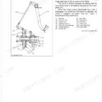
| Outline of Electronic Governor | 12 | Electronic Governor |
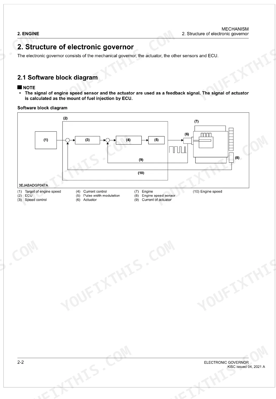
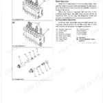
| Structure of Electronic Governor | 13-17 | Electronic Governor, Software Block Diagram, Component Parts, Control Unit, Speed Sensor |
| Function of Electronic Governor | 18-23 | Actuator, Electronic Governor, Fuel Control, Emergency Engine Stop, Failure Diagnosis, Circuit Protection, Smoke Reduce Control, CAN Communication (EGV06/EGV08) |
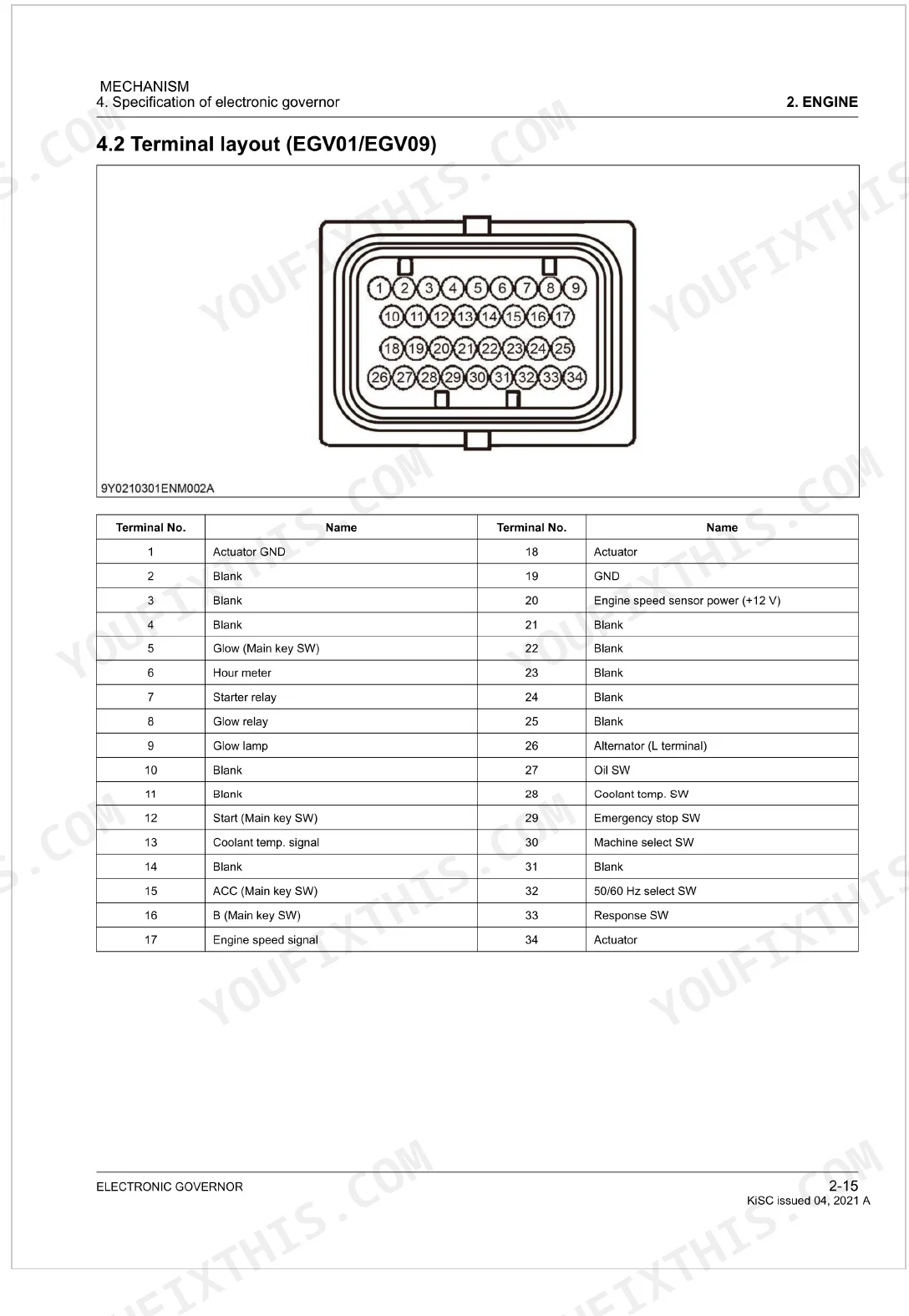
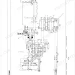
| Specification of Electronic Governor | 24-27 | Electronic Governor, Wiring Diagram, Terminal Layout (EGV01/EGV09), Terminal Layout (EGV06/EGV08) |
| Troubleshooting | 28-31 | Signal Pattern Sheet, Dtc List (EGV06/EGV08) |
| Diagnostic Procedure by Component | 32-37 | Checking Engine Speed Sensor, Checking Coolant Temperature Sensor, Checking Oil Pressure Switch, Checking Actuator, Checking Glow Plug Harness, Checking Alternator, Checking Speed Switch |
| Editor Information | 39 | Editor, Address, Phone, Fax, E-Mail, Kubota Corporation, Printed in Japan |
Quick Reference Specifications
| Specification | Value | Page |
|---|---|---|
| All Models | ||
| ECU Tightening torque | 7.0 to 9.0 N·m | p. 17 |
| ECU Operating voltage range | 10 to 16 V | p. 17 |
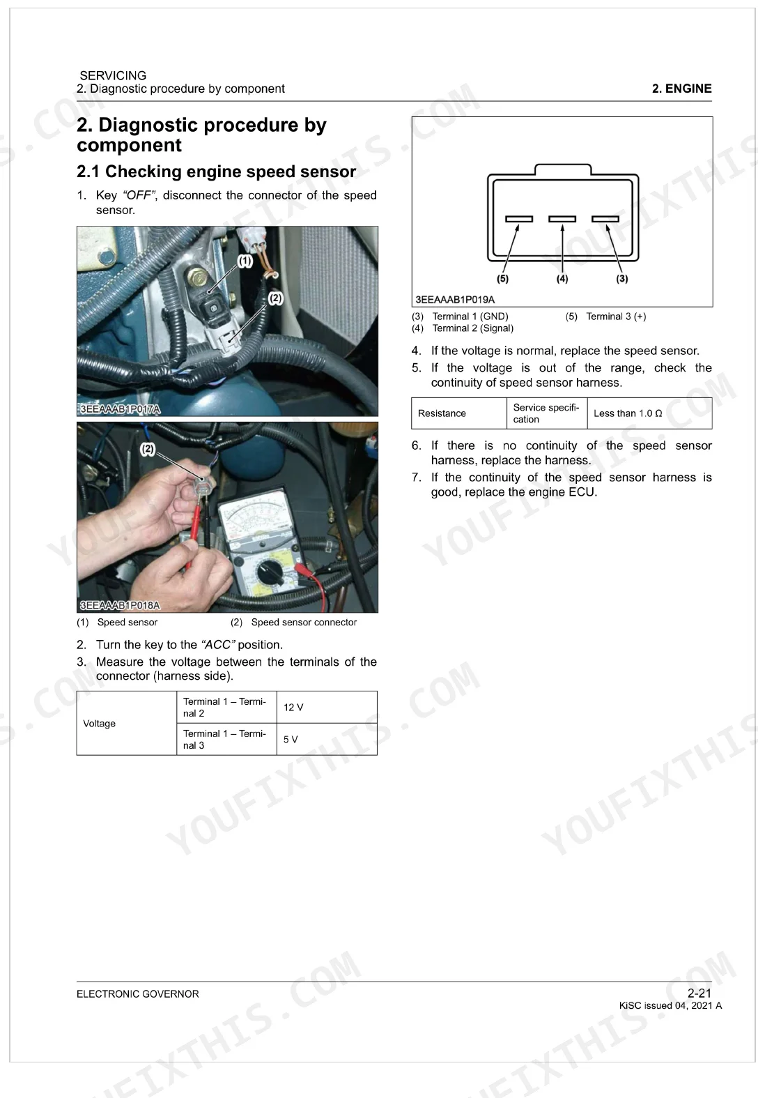
| Engine speed sensor connector voltage (Terminal 1-Terminal 2) | 12 V | p. 32 |
| Engine speed sensor harness continuity | Less than 1.0 Ω | p. 32 |
| Coolant temperature sensor connector voltage (Terminal 1-Terminal 2) | 5 V | p. 33 |
| Actuator connector voltage (Terminal 1-Terminal 2) | 12 V | p. 34 |
| Speed switch resistance (ON position) | 0 Ω | p. 35 |
| Battery voltage | 12 V | p. 36 |
| EGV01/EGV09 | ||
| ECU Operating temperature | -30 to 65 °C | p. 17 |
| EGV06/EGV08 | ||
| ECU Operating temperature | -30 to 80 °C | p. 17 |
Kubota EGV01–EGV09 Series Common Problems This Manual Covers
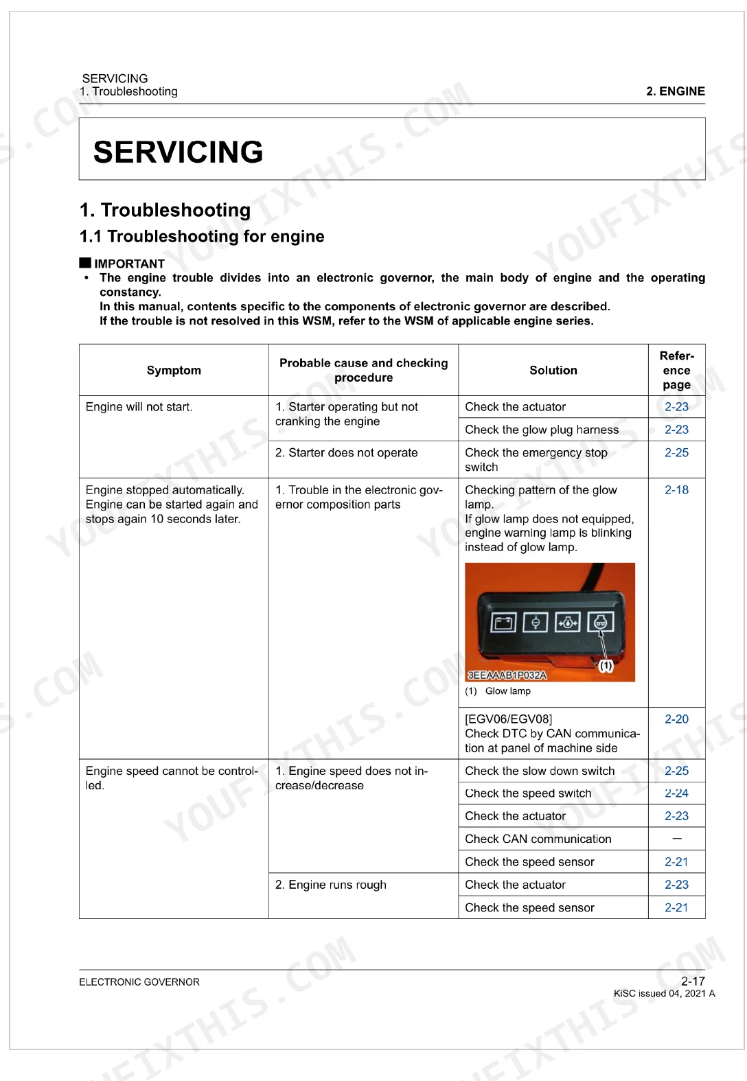
Kubota EGV diesel engine won't start, cranks normally but never fires
Check battery voltage first; it must read 12 V at the terminals (page 36). Confirm ECU supply is within 10 to 16 V. Verify the emergency stop switch is fully released. If those pass, inspect the engine speed sensor harness at page 32; harness continuity must be less than 1.0 Ω before suspecting the sensor itself.
Manual Section: Troubleshooting for engine p. 28Glow lamp blinks in a repeating sequence, engine shuts down unexpectedly
Count the exact blink sequence before the lamp resets; each pattern identifies a specific fault such as low oil pressure, alternator defect, or speed sensor failure. Confirm ECU supply voltage is within 10 to 16 V (page 17), then cross-reference the DTC list at page 31 to match the fault code for EGV06 and EGV08 units.
Manual Section: Signal pattern sheet p. 29Engine speed surges and hunts at idle, throttle response is erratic
Start at the troubleshooting table on page 28 for the engine speed control fault sequence. Inspect the actuator connector across Terminal 1 to Terminal 2; voltage must be 12 V (page 34). Push the actuator rod through its full stroke by hand and feel for binding. If the rod drags, remove and clean the actuator before checking the speed sensor.
Manual Section: Troubleshooting for engine p. 28Oil pressure warning light activates during normal load operation, engine stops automatically
Verify engine oil level is correct before touching sensor wiring. Check the troubleshooting procedures at page 28 for the oil pressure fault sequence. Measure battery voltage at the terminals; it must hold 12 V (page 36). Trace the oil pressure sensor harness for damaged insulation or loose connector pins using the wiring diagram at page 24.
Manual Section: Troubleshooting for engine p. 28Coolant temperature fault code stays active, engine runs rough or stops
Measure voltage between Terminal 1 and Terminal 2 at the coolant temperature sensor connector; correct reading is 5 V (page 33). If voltage is missing or unstable, trace the harness for chafing or corrosion using the wiring diagram at page 24. Replace the sensor only after harness checks pass and the fault persists after clearing.
Manual Section: Diagnostic procedure by component: Checking coolant temperature sensor p. 33Actuator rod not moving on command, engine stalls or holds fixed RPM
Probe the actuator connector between Terminal 1 and Terminal 2; it must read 12 V (page 34). Work the rod through its full stroke by hand; it should move freely with no sticking. If voltage is correct but the rod binds, pull the actuator and inspect for debris. Confirm harness resistance using the electrical pinout at page 26.
Manual Section: Diagnostic procedure by component: Checking actuator p. 34Frequently Asked Questions
How to troubleshoot engine won't start?
If the starter operates but the engine will not crank, check the actuator and the glow plug harness. If the starter does not operate at all, check the emergency stop switch. Procedures for these checks are on pages 2-23 and 2-25. p. 28
What torque specifications are listed?
For the ECU, the manual gives a tightening torque of 7.0 to 9.0 N·m. That equals 0.72 to 0.91 kgf·m, or 5.2 to 6.6 lbf·ft. p. 17
What are the common electrical problems?
Electrical faults show up as Diagnostic Trouble Codes (DTCs) or glow lamp blinking patterns. Typical ones include open or short circuits in sensors and harnesses (such as the accelerator pedal position sensor or water temperature sensor), alternator defects, excess voltage, and +B errors. Page 31 spells out specific failures like "Open circuit of sensor / harness, +B short circuit" for the accelerator position sensor. p. 29
What format is this Kubota EGV01–EGV09 Series manual in?
A 39-page Workshop Manual in searchable PDF, ready to download the moment checkout completes. Read it on a computer, tablet, or phone, with no shipping wait.
Can I print this Kubota EGV01–EGV09 Series manual?
Absolutely. No DRM or copy protection. Print the whole manual or just the pages you need. Any home or office printer works.
Does this Kubota EGV01–EGV09 Series Workshop Manual have electrical diagrams?
Yes. Full electrical schematics are included, with wire colors, connector locations, and circuit descriptions.


Reviews
There are no reviews yet.