


Part of the Kubota Repair Manuals.
Need the OEM service data for your L4400HST? This 110-page Kubota L4400HST workshop manual PDF (9Y111-02081) walks through the hydrostatic transmission, PTO clutch system, hydraulic circuit, steering, and full electrical system at factory depth. Inside you get hydraulic circuit schematics with complete fluid routing for both the steering and lift systems, full wiring diagrams covering the starting circuit and every safety switch, exploded views, and step-by-step disassembly and assembly procedures. Your maintenance intervals are mapped out at 50, 200, and 400 hours, with troubleshooting charts for the HST and electrical faults. Set the high-pressure relief valve between 33.3 and 36.3 MPa, then torque the HST control lever hex screw to 6.86–8.33 N·m. No more chasing HST faults with a test light and guesswork. Bookmarked for instant navigation; search any spec by keyword and pull it up on your phone right at the machine.
What's Inside This Kubota L4400HST Manual
| System | Pages | Key Topics |
|---|---|---|
| Safety Instructions | 4-11 | Safety First, Danger, Warning, Caution, Important, Note, Before Servicing and Repairing, Safety Starting |
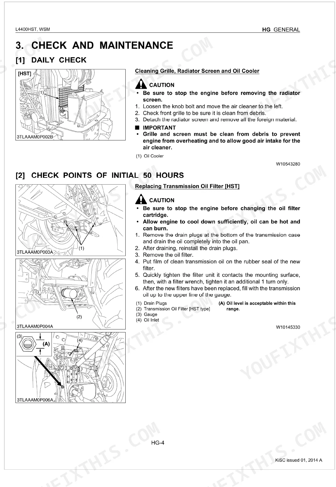
| General | 12-22 | Lubricants, Fuel and Coolant, Check and Maintenance, Daily Check, Check Points of Initial 50 Hours, Check Point of Every 50 Hours, Check Points of Every 200 Hours, Check Point of Every 400 Hours, Check Point of Every 2 Years |
| Engine | 23-25 | Engine Body, Fuel System |
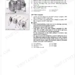
| Clutch | 26-30 | PTO Clutch, PTO Clutch Valve Condition, PTO Clutch Relief Valve Operating Pressure |
| Structure | 32 | Hydrostatic Transmission Section, PTO Clutch Section, Range Gear Shift Section, Front Wheel Drive Shift Section |
| Power Train | 33-44 | HST Power Train Layout, Gear Shift, Front Wheel Drive Shaft, Differential Gear, Rear Axle |
| PTO System | 45-48 | PTO Shaft, PTO Clutch Assembly, PTO Drive Gear |
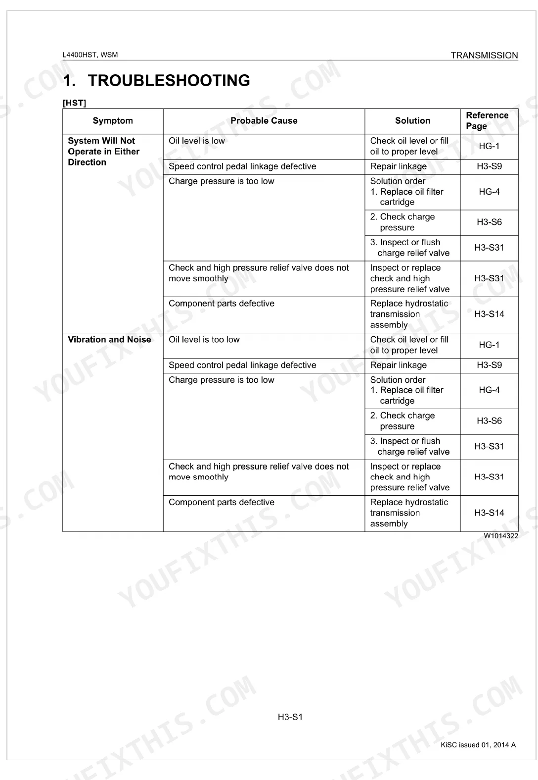
| Troubleshooting | 49-50 | Speed Control Pedal Linkage, Oil Filter Cartridge, Charge Relief Valve, High Pressure Relief Valve, Hydrostatic Transmission Assembly, Radiator Net |
| Servicing Specifications | 51 | High Pressure Relief Valve, Charge Relief Valve, HST Pedal, Cruise Control Lever |
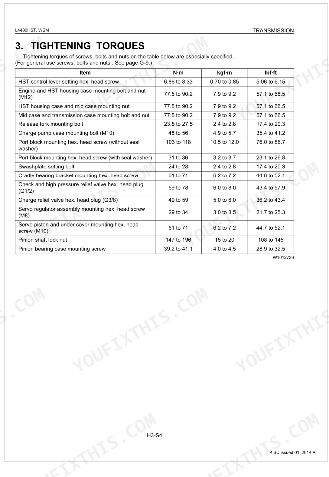
| Tightening Torques | 52 | HST Control Lever, Engine, HST Housing Case, Mid Case, Transmission Case, Release Fork, Charge Pump Case, Port Block |
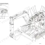
| Checking, Disassembling and Servicing | 53-76 | HST Assembly, Charge Pump Removal, Motor/Pump Shaft, Cylinder Block, Piston Assembly, Control Valve, Swashplate, Cradle Bearing |
| Servicing | 77-81 | Charge Pump, Pump Shaft and Motor Shaft, Cylinder Block Bore and Pistons, Piston Slipper, Cylinder Block Face, Valve Plate, Thrust Plate, Swashplate and Cradle Bearing |
| Steering | 82-87 | Hydraulic Circuit, Relief Valve (Power Steering) |
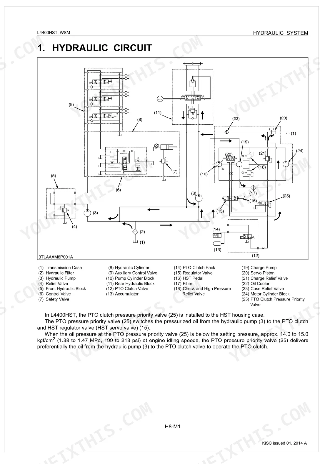
| Hydraulic System | 88-93 | Hydraulic Circuit, Cylinder Safety Valve |
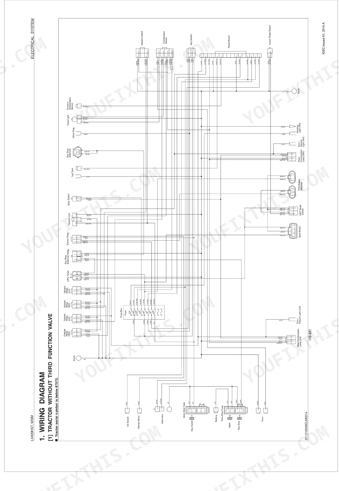
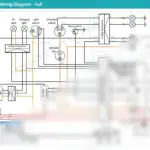
| Electrical System | 94-110 | Wiring Diagram, Tractor Without Third Function Valve, Starting System, Electric Circuit, Safety Switch, PTO Switch, HST Pedal Switch (HST Pedal Neutral Switch), Clutch Pedal Switch |
Quick Reference Specifications
| Specification | Value | Page |
|---|---|---|
| HST control lever setting hex. head screw torque | 6.86 to 8.33 N·m | p. 52 |
| Safety switch continuity (when pushed) | 0 Ω | p. 108 |
| Check and High Pressure Relief Valve Setting Pressure | 33.3 to 36.3 MPa | p. 51 |
| Engine net power | 32.1 kW (43.6 HP) / 2600 min⁻¹ (rpm) | p. 9 |
| Fuel tank capacity | 76 L (20.1 U.S.gals) | p. 9 |
| Engine crankcase (with filter) capacity | 7.6 L (8.0 U.S.qts) | p. 13 |
| Transmission case capacity | 40.0 L (10.6 U.S.gals) | p. 13 |
| Top Clearance (Engine) | 0.575 to 0.675 mm (0.0227 to 0.0265 in.) | p. 25 |
| PTO Clutch Valve Operating pressure | 2.25 to 2.45 MPa | p. 28 |
| Pinion shaft lock nut torque | 147 to 196 N·m | p. 52 |
| High Pressure Relief Valve Setting Pressure (Transmission) | 33.3 to 36.3 MPa | p. 51 |
| Relief Valve Setting Pressure (Steering) | 10.7 to 11.7 MPa | p. 85 |
Kubota L4400HST Common Problems This Manual Covers
Kubota L4400HST intermittent no-crank condition or tractor will not start when the key is turned
Test the safety switch circuits including the PTO, HST pedal, and clutch pedal switches. Verify safety switch continuity reads 0 Ω when pushed, as detailed on page 108. Inspect the wiring harness and starter motor connections if the battery is fully charged.
Manual Section: Electrical System p. 108Hydrostatic drive response feels weak and transmission exhibits a severe loss of power under load
Check the transmission case oil level and fill to the 40.0 L (10.6 U.S.gals) capacity listed on page 13. Inspect the high pressure relief valve setting. Test the pressure to confirm it falls between 33.3 to 36.3 MPa according to the specifications on page 51.
Manual Section: Transmission Troubleshooting: Loss of Power p. 51Tractor creeps forward or backward and machine will not stop in the neutral position
Adjust the speed control pedal linkage and neutral alignment. Torque the HST control lever setting hex head screw to 6.86 to 8.33 N·m as instructed on page 52. Inspect the components for excessive wear and replace any damaged linkage pins immediately.
Manual Section: Transmission Troubleshooting: Machine Will Not Stop in Neutral Position p. 52System exhibits poor loader lift capacity and obvious hydraulic oil leaks around hoses and fittings
Inspect all hydraulic lines and seals for visible leaks or damage. Review the hydraulic schematic on page 89 to trace the circuit. Check the steering relief valve setting pressure and confirm it measures 10.7 to 11.7 MPa as specified on page 85. Replace damaged hoses.
Manual Section: Hydraulic System p. 89Frequently Asked Questions
What torque specs are needed for Kubota L4400HST repairs?
Various torque specifications are provided for Kubota L4400HST repairs. For instance, the HST control lever setting hex. head screw requires a torque of 6.86 to 8.33 N·m (0.70 to 0.85 kgf·m, 5.06 to 6.15 lbf·ft). The engine and HST housing case mounting bolt and nut (M12) should be tightened to 77.5 to 90.2 N·m (7.9 to 9.2 kgf·m, 57.1 to 66.5 lbf·ft). p. 52
Why does my Kubota L4400HST lose power?
If your Kubota L4400HST loses power, several issues could be the cause, including low oil level, a defective speed control pedal linkage, or insufficient charge pressure. Other potential problems involve the check and high pressure relief valve not moving smoothly, or defective component parts within the hydrostatic transmission. p. 50
How do I troubleshoot a no-crank issue on a Kubota L4400?
To troubleshoot a no-crank issue on a Kubota L4400, check for a discharged or defective battery, a blown slow blow fuse, or a defective safety switch (PTO lever, HST pedal, and clutch pedal). Also, inspect the wiring harness for disconnections or improper connections, and verify if the starter motor or main switch is defective. p. 107
How to reset Kubota L4400HST HST
To adjust the HST neutral position, first stop the engine and set the cruise control lever to "OFF". Then, check and adjust the length 'a' of the HST control rod (2) to 230.5 to 231.5 mm (9.07 to 9.11 in.) and the length 'b' of the neutral rod (6) to 139.5 to 140.5 mm (5.49 to 5.53 in.) if they are not within the specified range. p. 55
How will I receive this Kubota L4400HST Workshop Manual?
This is a 110-page searchable PDF ready for immediate download. Works on any device, pull it up on your phone while you're under the hood. No shipping, no waiting.
Am I able to print pages from this manual?
No restrictions at all. Print individual pages, full chapters, or the entire manual. The PDF is completely unlocked.
Does this Kubota L4400HST manual include hydraulic schematics?
Full hydraulic system diagrams are included, covering circuits, valve locations, and hydraulic component specs for the Kubota L4400HST.


Reviews
There are no reviews yet.