


Part of the Kubota Repair Manuals.
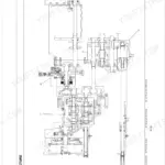
Factory coverage for all three AU-series front loaders sits in these 68 pages: the LA524AU-B, LA714AU-B, and LA854AU-B. The manual walks the hydraulic circuit, boom and bucket cylinder controls, and the full servicing specs. Schematics trace both the standard circuit and the optional third function valve routing, while wiring diagrams map the solenoid valve electrical circuit. Tightening torques cover hydraulic fittings, mounting hardware, and plugs, followed by sections on checking, disassembling, and servicing work. Set the LA714AU-B relief valve between 17.1 and 18.1 MPa (2489 to 2631 psi), then torque the main frame mounting bolts to 226 N-m (166 lbf·ft). When your loader is down and the dealer quotes three days, this hands you the factory answer now. Bookmarked by section and keyword-searchable, it opens on a phone or tablet right at the machine.
What's Inside This Kubota LA524AU-B, LA714AU-B, LA854AU-B Manual
| System | Pages | Key Topics |
|---|---|---|
| Information | 2-15 | - |
| General | 16-26 | Loader Identification, Lubricants |
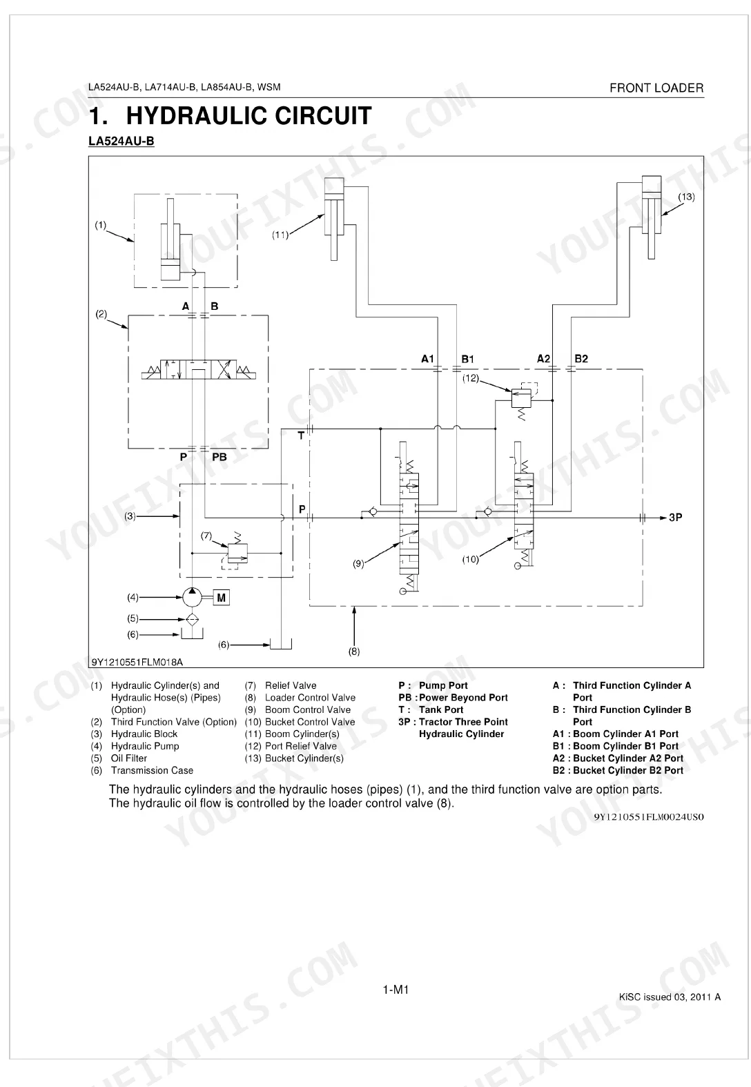
| Mechanism | 27-47 | Hydraulic Circuit, Control Valve Assembly (Structure, Boom Cylinder Control, Bucket Cylinder Control) |
| Servicing | 48-68 | Relief Valve, 3rd. Function Valve, Front Hydraulic Valve Main Switch, Control Valve, Bucket, Boom, Hydraulic Cylinder, Quick Hitch Frame |
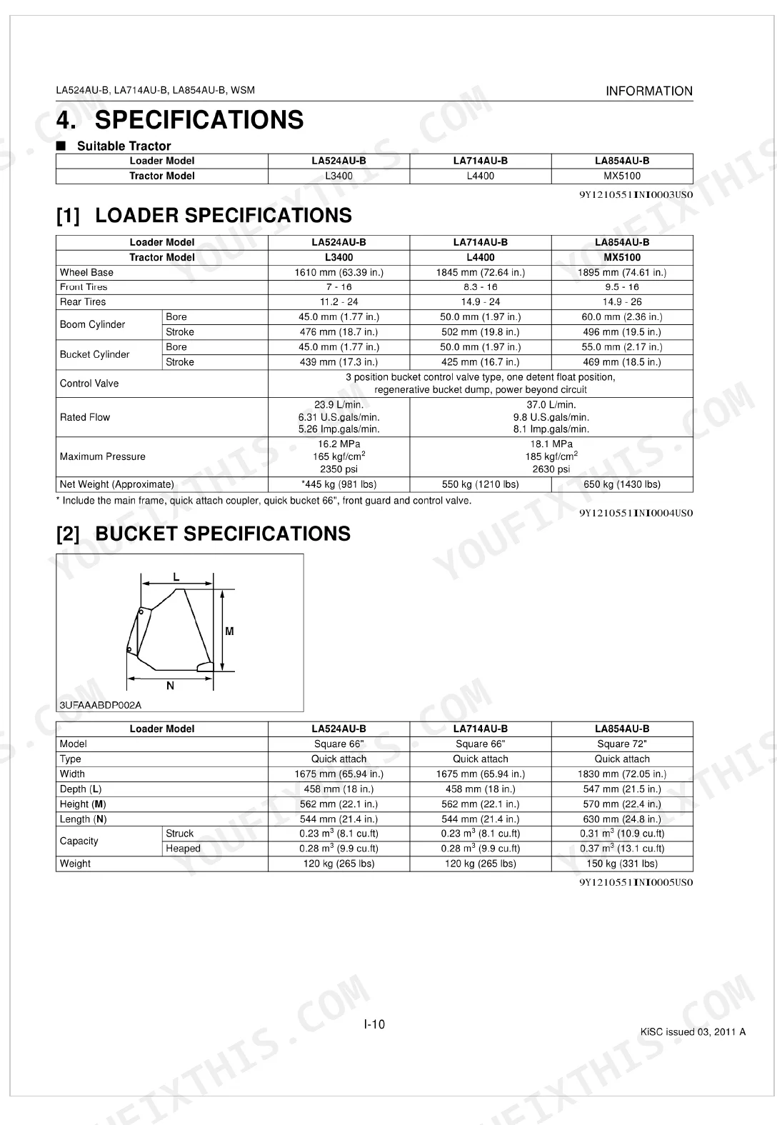
Quick Reference Specifications
| Specification | Value | Page |
|---|---|---|
| LA714AU-B | ||
| Relief valve setting pressure | 17.1 to 18.1 MPa (175 to 185 kgf/cm², 2489 to 2631 psi) | p. 54 |
| All Models | ||
| Main frame mounting bolt and nut torque | 226 N-m (23 kgf-m, 166 lbf·ft) | p. 26 |
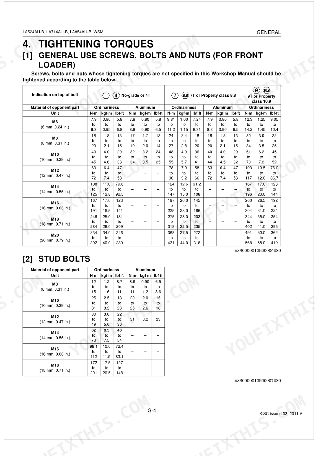
| Front guard mounting bolt torque | 124 to 147 N·m (12.6 to 15.0 kgf·m, 91.2 to 108 lbf·ft) | p. 51 |
| Adapter and elbow torque | 48 to 54 N-m (4.9 to 5.5 kgf·m, 35 to 40 lbf·ft) | p. 51 |
| Nipple torque | 40 to 59 N-m (4.0 to 6.0 kgf·m, 29 to 44 lbf·ft) | p. 51 |
| Control valve cover mounting bolt torque | 9.81 to 11.2 N·m (1.00 to 1.14 kgf·m, 7.24 to 8.31 lbf·ft) | p. 51 |
| Control valve mounting bolt torque | 25 to 27 N-m (2.5 to 2.7 kgf·m, 18 to 20 lbf·ft) | p. 51 |
| Hose fitting, Flare nut (UNF) torque (9/16 thread size) | 22 to 25 N-m (2.3 to 2.5 kgf.m, 17 to 18 lbf.ft) | p. 23 |
| Hose fitting, Flare nut (UNF) torque (3/4 thread size) | 36 to 40 N-m (3.7 to 4.0 kgf.m, 27 to 29 lbf.ft) | p. 23 |
| Adjustable elbow, Adapter (O-ring port) (UNF) torque (9/16 thread size) | 37 to 44 N-m (3.8 to 4.4 kgf.m, 28 to 32 lbf.ft) | p. 23 |
| Adjustable elbow, Adapter (O-ring port) (UNF) torque (3/4 thread size) | 48 to 54 N-m (4.9 to 5.5 kgf.m, 36 to 39 lbf.ft) | p. 23 |
| LA854AU-B | ||
| Sub frame mounting bolt and nut torque | 226 N-m (23 kgf·m, 166 lbf·ft) | p. 51 |
Kubota LA524AU-B, LA714AU-B, LA854AU-B Common Problems This Manual Covers
Loader stalls or hesitates when you try to raise and curl at the same time
Check the control lever linkage and valve spools for binding. During reassembly, set the rod end joint length A precisely to 115.3 to 116.3 mm as shown on page 58. Clear any debris that restricts spool movement.
Manual Section: Control Valve Assembly p. 58Bucket will not lower unless another hydraulic function is used at the same time
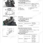
Test the control valve solenoids with a multimeter. Solenoid valve resistance should read 4.4 to 5.8 ohms at 20 degrees Celsius (page 55); replace the solenoid if it falls outside that range. Inspect the spool for scoring or sticking.
Manual Section: Boom Does Not Lower p. 55Loader arms or crossbar appear twisted or out of alignment after uneven side loading
Measure each cylinder against the piston rod bend allowable limit of 0.25 mm given on page 50, and inspect the main frame for structural damage. Torque all main frame mounting bolts to 226 N-m per page 26 to bring the arms back into alignment.
Manual Section: Checking p. 50Hydraulic functions work intermittently or fail under heavy load near the adjustable elbow fittings
Inspect the hydraulic circuit for pressure leaks at the O-ring ports. Torque the 9/16 thread-size adjustable elbows to 37 to 44 N-m as outlined on page 23. If the fluid looks milky or heavily aerated, drain the system and clean the filter.
Manual Section: Hydraulic Circuit p. 23Frequently Asked Questions
What is the torque spec for Kubota LA524AU-B mounting bolts?
On the Kubota LA524AU-B, torque the main frame mounting bolt and nut to 226 N-m (166 lbf·ft). The front guard mounting bolts call for 124 to 147 N·m (91.2 to 108 lbf·ft). p. 51
What is the solenoid valve resistance spec for the Kubota LA714AU-B front loader?
Test the solenoid valve with a multimeter. Resistance should read 4.4 to 5.8 ohms at 20 degrees Celsius (page 55 of the Kubota LA714AU-B Front Loader Shop Manual). Replace the solenoid if it falls outside that range. p. 55
What is the piston rod bend allowable limit for Kubota LA524AU-B cylinders?
The piston rod bend allowable limit for Kubota LA524AU-B and LA854AU-B cylinders is 0.25 mm (page 50). Measure each cylinder rod; if it exceeds this limit, inspect the main frame for structural damage and replace the rod if necessary. p. 50
What is the torque spec for adjustable elbow fittings on the Kubota LA524AU-B hydraulic circuit?
Torque the 9/16 thread-size adjustable elbows to 37 to 44 N-m as outlined on page 23 of the Kubota LA524AU-B, LA714AU-B, LA854AU-B Front Loader Shop Manual. Inspect the hydraulic circuit for O-ring port pressure leaks if functions fail under heavy load. p. 23
Is this Kubota LA524AU-B, LA714AU-B, LA854AU-B Shop Manual a digital download?
Yes. Its a 68-page searchable PDF, available the moment checkout completes. Read it on a computer, tablet, or phone with no shipping wait.
Is this Kubota LA524AU-B, LA714AU-B, LA854AU-B Shop Manual printable?
Yes, print as many copies as you like; there are no restrictions. Plenty of mechanics print just the section they need and carry it to the shop floor.
Are electrical wiring diagrams included in this Kubota LA524AU-B, LA714AU-B?
Yes. Youll find full electrical schematics with wire routing diagrams, connector identification, and circuit descriptions.


Reviews
There are no reviews yet.