


Part of the Kubota Repair Manuals.
Looking for the Kubota LM2605 workshop manual PDF? OEM manual #9Y111-13814 runs 184 pages and stays on one job: full service and repair of the LM2605 Front Loader in both open center and closed center load-sensing configurations. Hydraulic schematics trace oil flow through every control lever position, from boom-up to float to roll-back, while the wiring diagrams cover both electrical variants down to joint connector pinout locations. A troubleshooting section alongside a DTC diagnostic code list covers the most common faults, with step-by-step servicing and tightening torques for hydraulic fittings and mounting hardware. Maximum hydraulic pressure is 19.6 MPa. Torque the M27 main frame mounting bolts to 720-800 N·m and the M20s to 400-430 N·m. Bookmarked and keyword-searchable, it opens on a tablet so you can read it right at the machine.
What's Inside This Kubota LM2605 Manual
| System | Pages | Key Topics |
|---|---|---|
| Supplementary Information | 3 | Model Name and Related Manuals |
| Record of Revisions | 4-8 | - |
| Safety | 9-19 | Safety First, Preparing for Emergencies, Working Cautions, Safety Labels, Care of Danger, Warning and Caution Labels (Boom Up Position), Starting Machine Safely |
| General | 20-46 | Tightening Bolts and Nuts, Applying Thread-Locking Fluid (Operational Specification), Installing Circlips, Installing Spring Pins, Handling Split Pin |
| Maintenance | 47-55 | Maintenance Checklist, Lubricants, Check and Maintenance |
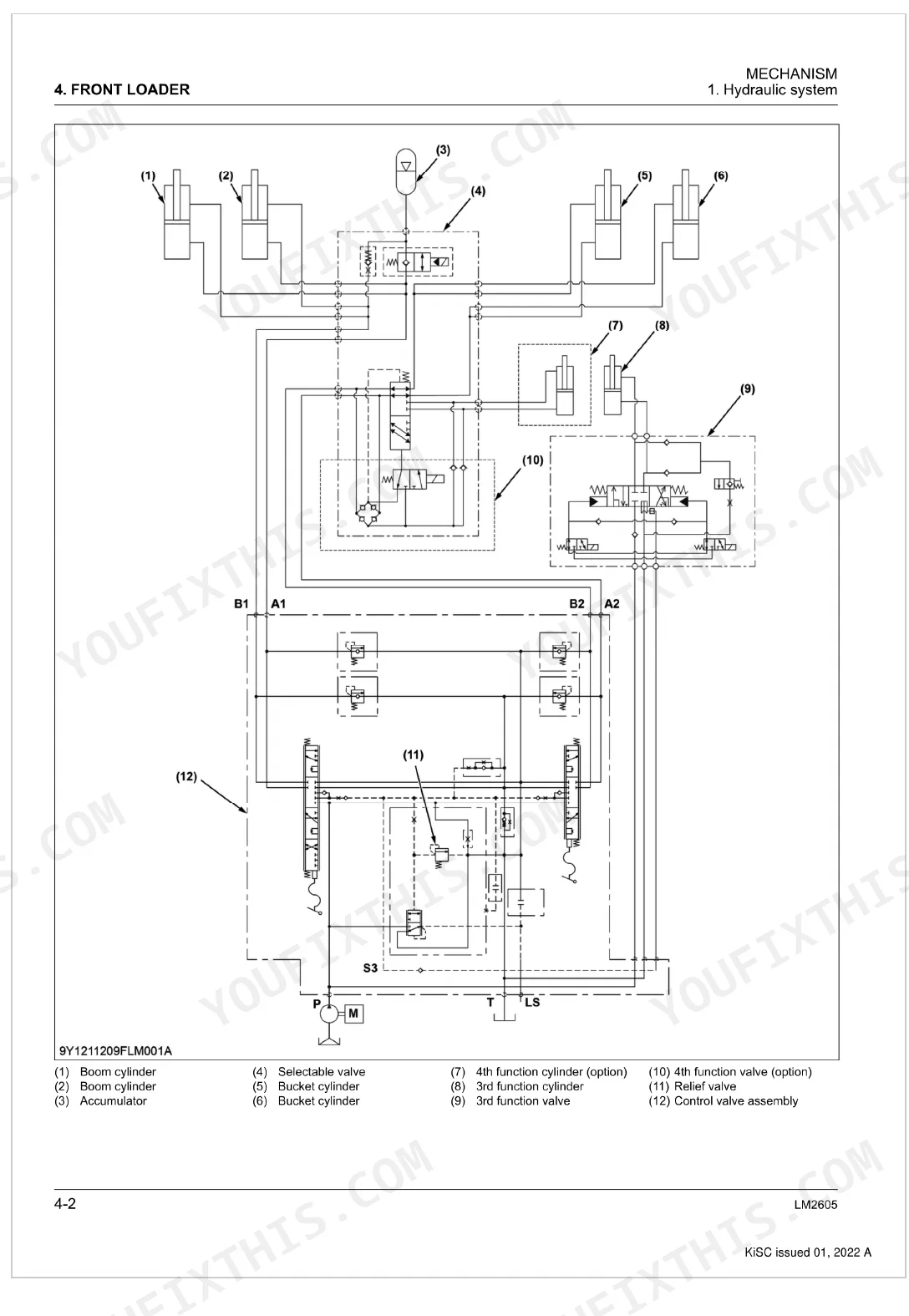
| Control Lever at Neutral Position | 57-65 | Control Valve, Hydraulic System, Open Center Model, Structure of Hydraulic System, Mechanism, Function, Feature of Hydraulic System, Oil Flow of Hydraulic System |
| Function of Control Valve | 66-81 | Control Lever at Roll-Back Position, Control Lever at Boom Down Position, Control Lever at Boom Up Position, Flow of Closed Center, Structure of Closed Center, X17 Joint Connector, X59 Joint Connector, Main Valve Lower Connector |
| Control Lever at Float Position | 82-89 | Control Lever at Boom Up Position, Control Lever at Neutral Position, Control Lever at Boom Down Position, Checking Voltage |
| Selectable Valve at Original Position | 90-97 | Control Lever at Dump Position, Control Lever at Roll-Back Position, Checking Voltage, Checking Continuity, Checking Resistance, Selectable Valve, Structure of Selectable Valve, Reinstalling |
| 3rd Function Valve When Direction Valve Is Open | 98-105 | Function of 3rd Function Valve, Selectable Valve at 4th Function Position (Option), 3rd Function Valve Assembly, Structure of 3rd Function Valve, 3rd Function Valve Assembly (Open Center Model), Removing From Control Valve, Pushing Activation Switch a, 3rd Function Valve at Neutral Position |
| Structure of Hydraulic Accumulator | 106-113 | Operating the Activation Switch a, Function of 3rd Function Valve, 3rd Function Valve Assembly (Closed Center with Load Sensing Model), Structure of 3rd Function Valve, 3rd Function Valve at Neutral Position, 3rd Function Valve When Direction Valve Is Open, Operating Activation Switch B, Hydraulic Accumulator |
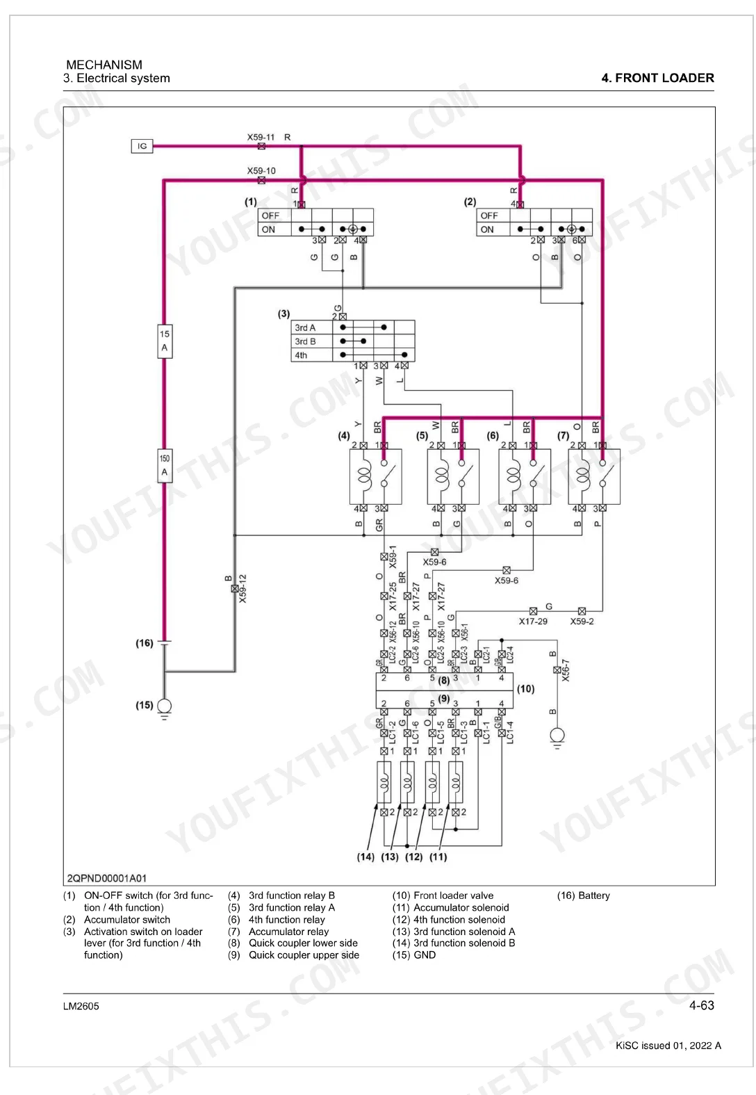
| Closed Center Load Sensing Model | 114-121 | Function of Mechanical Self-Leveling, Mechanical Self-Leveling, Function of Hydraulic Accumulator, Self-Leveling System, Structure of Mechanical Self-Leveling, Electrical System, Open Center Model, Outline of Open Center Electrical Diagram |
| Flow of Closed Center Electrical Current | 122-180 | Structure of Closed Center Electrical Circuit, Location of Joint Connector, X59 Joint Connector, X17 Joint Connector, X56 Joint Connector, Main Valve Lower Connector, Main Valve Upper Connector |
Quick Reference Specifications
| Specification | Value | Page |
|---|---|---|
| Main frame mounting bolt (M27) tightening torque | 720 to 800 N·m (73.5 to 81.5 kgf·m, 531 to 590 lbf·ft) | p. 140 |
| Main frame mounting bolt (M20) tightening torque | 400 to 430 N·m (40.8 to 43.8 kgf·m, 295 to 317 lbf·ft) | p. 140 |
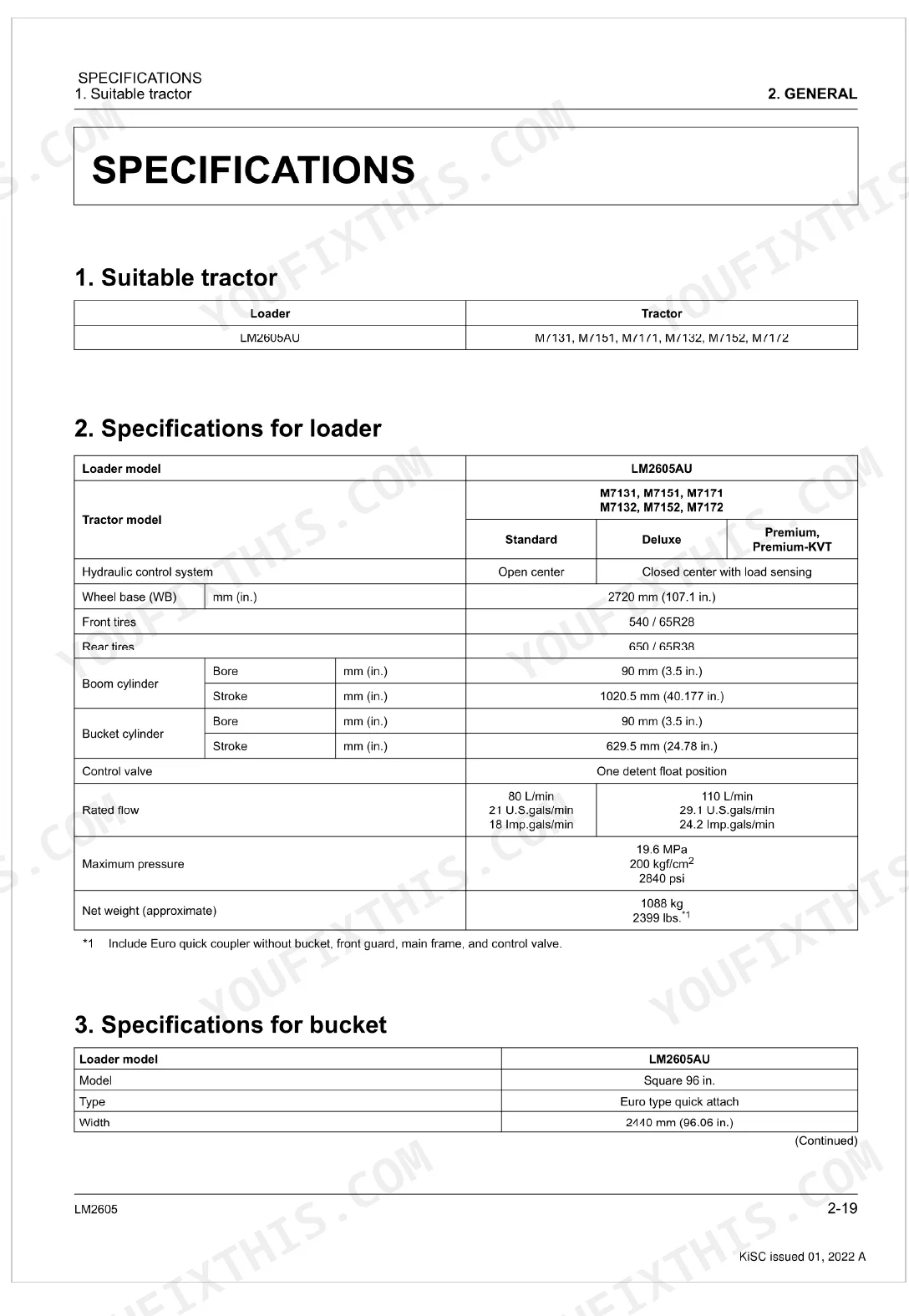
| Wheel base (WB) | 2720 mm | p. 39 |
| Maximum pressure (Hydraulic) | 19.6 MPa | p. 39 |
| Net weight (approximate) | 1088 kg | p. 39 |
| Maximum lift height (to bucket pivot pin) | 4250 mm | p. 40 |
| Lift capacity (Bucket pivot pin, max. height) | 2620 kg | p. 41 |
| Transmission case (Power shift model) capacity | 85 L | p. 50 |
| Transmission case (CVT model) capacity | 80 L | p. 50 |
| Relief valve setting pressure | 19.5 to 21.0 MPa | p. 134 |
| Main frame mounting bolt (M27) torque | 720 to 800 N·m | p. 140 |
| Front guard nut torque | 197 to 225 N·m | p. 140 |
Kubota LM2605 Common Problems This Manual Covers
Kubota LM2605 boom raises slower than normal, cycle time noticeably longer under load
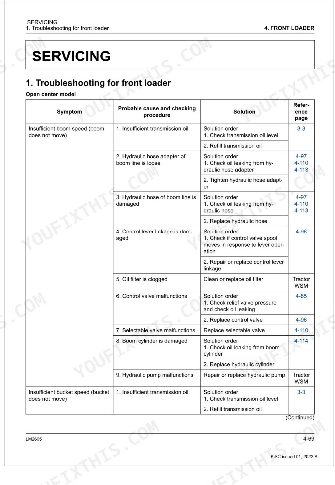
Check the relief valve setting pressure at the control valve test port on page 141. Pressure must read 19.5 to 21.0 MPa at full load. If pressure is low, inspect for a worn or sticking relief valve spool before adjusting. Also verify hydraulic fluid level in the transmission case: Power Shift models take 85 L, CVT models take 80 L (page 50). Run the troubleshooting flowchart to isolate whether the fault is in the pump circuit or the boom solenoid.
Manual Section: Front Loader Troubleshooting (Open Center Model) p. 125Bucket curl and dump response is sluggish, tip load feels reduced
Inspect the bucket solenoid for a DTC against the error code list on page 177. Pull the solenoid connector and measure resistance; an open or shorted coil will read outside spec. Next, run the control valve diagnostics to confirm relief valve setting pressure sits within 19.5 to 21.0 MPa on page 141. If the solenoid checks out, look at the hydraulic hoses for internal collapse or kinked lines at the bucket circuit.
Manual Section: Control Valve Diagnostics p. 125Self-leveling stops working mid-cycle, bucket tilts unpredictably during boom raise
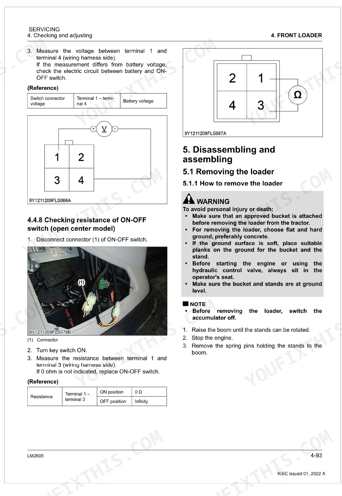
Verify the activation switch is receiving voltage and that resistance is within spec using the switch diagnostics on page 147. A failed switch is the most common cause. Also inspect the 3rd function valve per page 143: resistance on the open center model solenoid should read 8 Ω (page 134). If both check out, pull the troubleshooting flowchart and trace the self-leveling circuit step by step. Confirm wiring continuity back to the relay using the relay voltage checks on page 146.
Manual Section: Relay and Switch Diagnostics p. 1263rd function hydraulic attachment gets no flow, actuator won't move in either direction
Start with the DTC list to check for a 3rd function solenoid fault code on page 177. Disconnect the solenoid and measure resistance: it should read 8 Ω for open center models (page 134). If the coil is good, confirm the 3rd function valve is operating correctly per page 143 for your model type. Measure the ON-OFF switch resistance and voltage on page 148. Make sure the control lever is fully engaging and that no mechanical binding is present in the valve linkage.
Manual Section: 3rd Function Valve Diagnostics p. 127Loader hardware loose after first 20-50 hours, clunking noise from main frame attachment points
Re-torque the main frame mounting bolts on the first service at 20 to 30 hours per the maintenance schedule on page 48. M27 mounting bolts require 720 to 800 N·m; M20 bolts require 400 to 430 N·m (page 140). Use a calibrated torque wrench and work in a cross pattern. After re-torque, grease all fittings as required every 10 hours. Hardware re-checks should then follow every 50 hours per page 48.
Manual Section: Maintenance p. 48Accumulator function not cycling correctly, hydraulic cushioning absent on boom float
Test the accumulator solenoid valve using the diagnostics on page 144. Measure solenoid voltage at the connector and compare against spec. If voltage is present but the solenoid is not actuating, pull it and inspect for contamination or a stuck spool. Then verify the accumulator switch resistance and voltage on page 146. Cross-reference any stored fault codes for accumulator solenoid DTCs on page 177 before ordering parts.
Manual Section: Selectable Valve Diagnostics p. 129Frequently Asked Questions
What are the recommended service intervals?
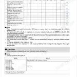
Service intervals run from daily to every 50 hours. Daily, check transmission fluid level, hydraulic hoses, hardware, and the quick attach coupler. Grease all fittings every 10 hours. Re-tighten hardware at 20 to 30 hours, then verify loader hardware torque every 50 hours. p. 48
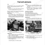
What fluids and capacities does this machine require?
The transmission case takes Kubota UDT or SUPER UDT fluid: 85 L (90 U.S.qts, 75 Imp.qts) on the Power shift model and 80 L (85 U.S.qts, 70 Imp.qts) on the CVT model. For grease fittings and control lever linkage joints, use Moly Ep type grease until it overflows. p. 50
What are the hydraulic system specifications?
Specs depend on the model. The control system is either open center or closed center with load sensing. Both boom and bucket cylinders use a 90 mm (3.5 in.) bore; boom stroke is 1020.5 mm (40.177 in.) and bucket stroke is 629.5 mm (24.78 in.). Rated flow is 80 L/min on open center and 110 L/min on closed center, at a maximum pressure of 19.6 MPa (200 kgf/cm², 2840 psi). p. 39
What torque specifications are listed?
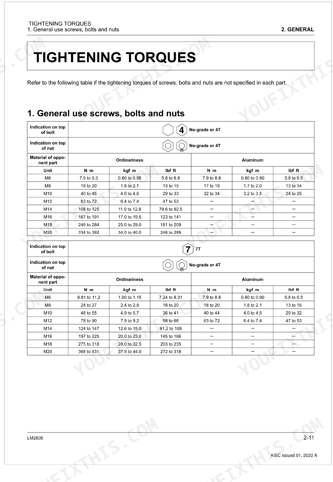
Torque values are listed by fastener. General hardware: M6 bolts (No-grade or 4T) take 7.9 to 9.3 N·m and M8 bolts (7T) take 24 to 27 N·m. Hydraulic fittings such as hose size 02 (1/8 thread) need 13.8 to 15.6 N·m. On the loader itself, the hydraulic hose (green tape) is 22 to 25 N·m, the main frame mounting bolt (M27) is 720 to 800 N·m, and the front guard nut is 197 to 225 N·m. p. 140
Is this Kubota LM2605 Workshop Manual a digital download?
Yes, it is a 184-page searchable PDF ready for immediate download. Works on any device, so pull it up on your phone while you're under the hood. No shipping, no waiting.
Is this Kubota LM2605 Workshop Manual printable?
None at all. The PDF is DRM-free, so print whatever sections you want to take out to the shop. Standard letter or A4 paper works fine.
Does this Kubota LM2605 Workshop Manual have electrical diagrams?
Yes. Full electrical schematics are included, with wire colors, connector locations, and circuit descriptions.


Reviews
There are no reviews yet.