
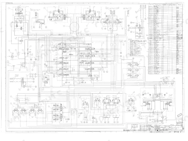


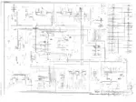
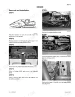
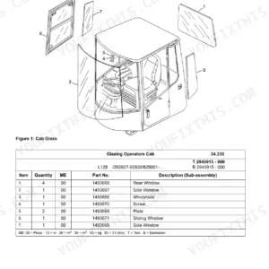
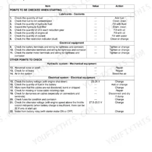
An hour from now you could be checking main relief pressure against the factory table: the Link-Belt 240LX service manual PDF, book number Cre 7-29880LX, puts 600 pages of shop procedure for your crawler excavator in front of you. Hydraulic and electrical schematics in large format close out the book, tracing circuits from the pilot blocks and six stack solenoid valve through to the swing motor, while the electrical section devotes a substantial run of pages to component location, operating principles, and troubleshooting. Undercarriage coverage runs from track set removal through idler and tension shock absorber service. Measure a bucket cylinder foot pin against its 3.14 inch standard, then pull the travel motor to final drive bolts to 197-230 lb-ft. A relief valve set by guesswork buys you a second teardown. With a real text layer and bookmarks for each system, the number you type is the page you land on.
What's Inside This Link-Belt 240LX Manual
| System | Pages | Key Topics |
|---|---|---|
| General Information | 5-36 | Safety Precautions, Standard Torque Data, General Specifications |
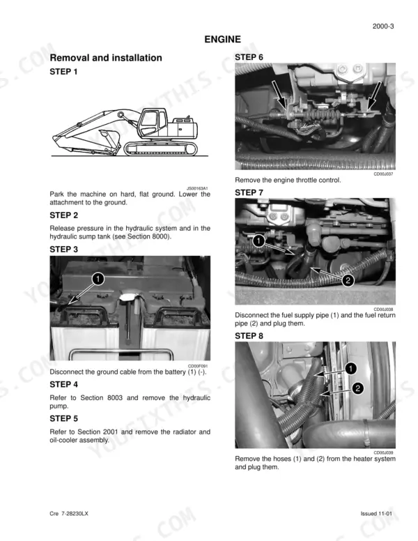
| Engine | 37-50 | Removal and Installation, Radiator and Oil Cooler |
| Fuel System | 51-56 | Fuel Tank Removal and Installation |
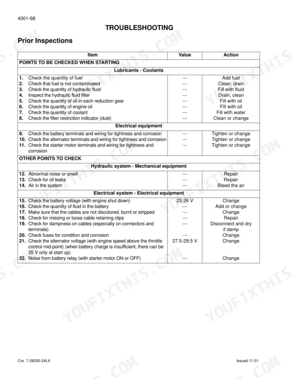
| Electrical System | 57-160 | Location of Components, Basic Operating Principles, Troubleshooting, Electrical Inspection of Components |
| Undercarriage | 161-234 | Tracks Set Removal and Installation, Upper and Lower Rollers, Sprocket Removal and Installation, Idler Wheel and Tension Shock Absorber |
| Drive Train | 235-266 | Drive Motor and Final Drive Transmission Removal and Installation, Drive Motor and Final Drive Transmission Disassembly and Assembly, Swing Reduction Gear, Removal and Installation |
| Depressurising and Decontaminating the Hydraulic System | 267-276 | Depressurizing, Vacuum Pump, Bleeding Components, Decontamination, Hydraulic System Cleaning |
| Specifications, Troubleshooting, Checks and Hydraulic Pressure Settings | 277-304 | Hydraulic Pressure Settings, Troubleshooting, Pilot System Relief Valve, Main Relief Valve, Travel Mistracking Test |
| Hydraulic Sump Tank Removal and Installation | 305-310 | Hydraulic Sump Tank, Removal, Installation, Suction Hoses |
| Main and Pilot Pumps Removal and Installation | 311-322 | Main Hydraulic Pump, Pilot Pump, Pump Coupling, Removal, Installation |
| Main Hydraulic Control Valve Removal and Installation | 323-328 | Main Control Valve, Removal, Installation, Central Frame |
| Attachment Cylinders Removal and Installation | 329-348 | Boom Cylinder, Arm Cylinder, Bucket Cylinder, Removal, Installation |
| Rotating Joint Removal and Installation | 349-352 | Rotating Joint, Removal, Installation, Hoses |
| Pilot Function Blocks and Solenoid Valves | 353-544 | Travel Pedal Block, Hand Joystick Control, Six Stack Solenoid Valve, Cushion Control, Hose Burst Check Valve, Swing Motor |
| Upperstructure | 545-600 | Turntable and Counterweight, Boom, Dipper and Bucket, Seat and Safety Belt, Cab and Cab Equipment, Air Conditioning Troubleshooting, Air Conditioning Unit Disassembly and Assembly |
Quick Reference Specifications
| Specification | Value | Page |
|---|---|---|
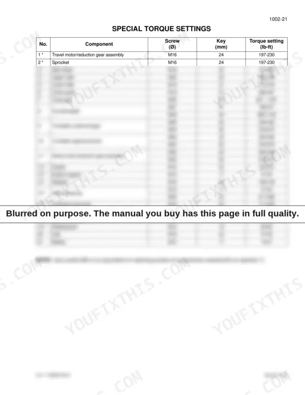
| Travel motor/reduction gear assembly torque setting | 197-230 lb-ft | p. 33 |
| Bucket cylinder foot/Arm pin diameter standard | 3.14 in | p. 31 |
| Bucket cylinder foot/Arm ring diameter standard | 3.14 in | p. 31 |
| Hydraulic pump torque setting | 47-54 lb-ft (M10) and 271-366 lb-ft (M20) | p. 33 |
| Upper roller torque setting | 384-448 lb-ft | p. 33 |
| Lower roller torque setting | 274-318 lb-ft | p. 33 |
| Idler wheel torque setting | 197-230 lb-ft | p. 33 |
| Idler wheel dimension A | 11.16 to 11.24 inches | p. 202 |
| Oil level, fill plug and oil drain plug torque | 3.6 to 8 lb-ft (5 to 11 Nm) | p. 236 |
| Hydraulic motor - Screw 1/16 NPTF torque | 7±0.7 lb-ft (10 ± 1 Nm) | p. 242 |
| Motor retaining screw on the reduction gear | 217 lb-ft (294.3 Nm) | p. 257 |
| Cover retaining screws | 21.5 lb-ft (29 Nm) | p. 377 |
Link-Belt 240LX Common Problems This Manual Covers
Link-Belt 240LX stick drifts inward under load, arm won't hold position with bucket loaded
Depressurize the system first using the procedure on page 267, then gauge main relief pressure against the 4975 psi standard listed on page 20. If pressure checks good, swap the stick load-hold check valve with a known-good unit to isolate the leak, then pull and reseal the arm cylinder if drift continues.
Manual Section: Specifications, Troubleshooting, Checks and Hydraulic Pressure Settings p. 277Swing brake won't release, upper structure swings slow or jerky in both directions
Check pilot circuit pressure feeding the swing brake release port before condemning the motor. Test relief settings using the pressure checks starting on page 277. If the brake releases only with test pressure applied, pull the swing motor and inspect it; torque the motor retaining screws to 217 lb-ft (294.3 Nm) on reinstall, spec on page 257.
Manual Section: Specifications, Troubleshooting, Checks and Hydraulic Pressure Settings p. 277All hydraulic functions slow and weak once oil gets hot, main pump whines at idle
Verify oil level against the 32 gal reservoir capacity on page 19 and change filters before opening the pump. Test main relief at 4975 psi per page 20. Inside the pump, measure piston-to-bore play against the 0.0015 / 0.0026 in limits and replace shoes worn below 0.18 in thickness, specs on page 377.
Manual Section: Main and Pilot Pumps Removal and Installation p. 311Machine tracks crooked on level ground, one final drive weeps gear oil at the cover
Run the travel mistracking test described in the pressure checks section starting on page 277. Drain the leaking final drive, inspect the oil for metal, and refill; torque the drain, level and fill plugs to 3.6 to 8 lb-ft (5 to 11 Nm) per page 236. If mistracking continues, swap travel lines side to side to isolate the motor.
Manual Section: Drive Train p. 235Tracks loose and throwing on turns, idler wheels worn, track tension won't hold adjustment
Measure idler wheel wear against the dimension A standard of 11.16 to 11.24 inches on page 202 and replace any idler below the limit. Torque idler wheel bolts to 197-230 lb-ft and lower roller bolts to 274-318 lb-ft per the chart on page 33, then grease the tension cylinder and recheck sag after a full shift.
Manual Section: Undercarriage p. 202Frequently Asked Questions
How do I access diagnostic fault codes on a Link-Belt 240LX?
To access the diagnostic mode, press the travel mode and work mode switches simultaneously for a minimum of 3 seconds. Once in this mode, you can navigate to the 'Diagnostic code' screen to view active faults. p. 106
How do I reset a Link-Belt 240LX fault code?
To erase diagnostic data, press the work mode switch for a minimum of 10 seconds while in the diagnostic mode until the audible warning device sounds. This will clear the stored fault codes. p. 106
What are the torque specifications for the engine retaining screws on a Link-Belt 240LX?
The torque specifications for the engine retaining screws are found in Section 1002. According to the special torque settings table, the engine retaining screws (M16) should be tightened to 195-231 lb-ft. p. 33
What is the capacity of the hydraulic fluid reservoir for the 240LX?
The hydraulic fluid reservoir capacity for the 240LX is 32 gallons. p. 19
What is the correct torque for the main relief valve (standard pressure) on the 240LX?
The main relief valve (standard pressure) is set to 4975 ± 44 psi. p. 20
Is this Link-Belt 240LX manual a PDF I download?
All 600 pages arrive as one searchable PDF at checkout. Read it at the desk, then take the phone out to the machine.
Can I print just the pages I need from this Link-Belt 240LX manual?
Yes. Many mechanics print the section they need for their own shop and bring it to the bench.



Reviews
There are no reviews yet.