
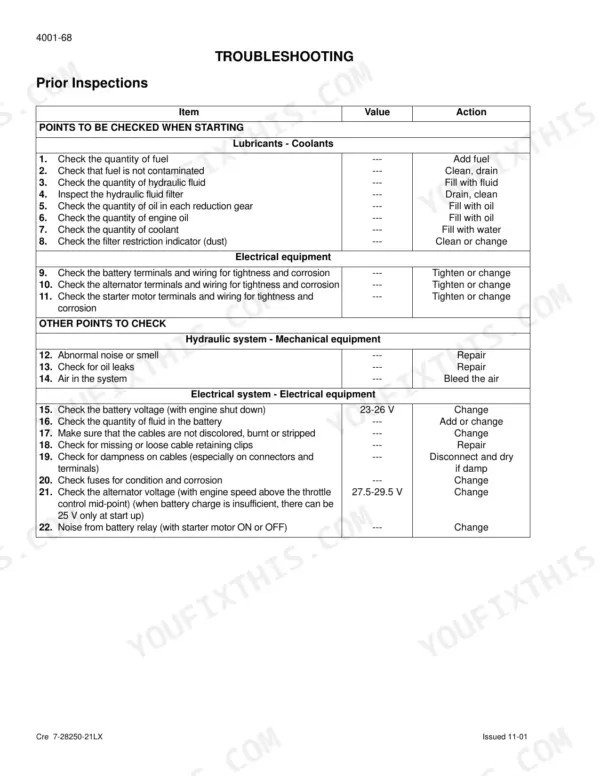
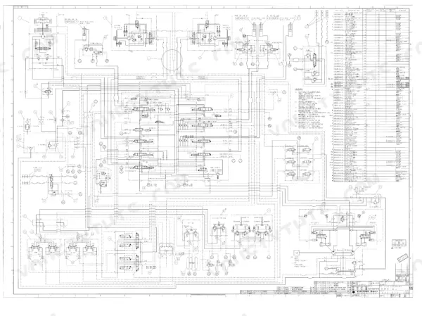
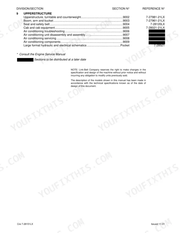

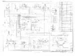
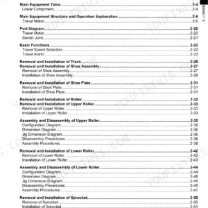
Chasing travel drift or a soft swing brake on a Link-Belt 210LX puts you deep in the pilot circuit, and hydraulics is where this shop manual spends close to half its 602 pages; the rest of this Link-Belt 210LX service manual PDF, factory book number 7-28151LX for the crawler excavator, covers engine removal, undercarriage, drive train, and cab work. Large format hydraulic and electrical schematics ride in the back pocket, backing an electrical section built around component locations and troubleshooting charts. Teardown procedures for the main pump, control valve, swing motor, and final drive transmissions each end in pressure checks and reassembly torques. Verify a minimum brake pressure of 421 psi at the swing motor and holding torque of at least 543.4 lb-ft before you call it done. Bleeding a system twice because one pressure was off costs a crew a day. Bookmarked, text-searchable, and ready to download, so the 210LX tracks out under its own power again.
What's Inside This Link-Belt 210LX Manual
| System | Pages | Key Topics |
|---|---|---|
| General Information | 1-36 | Safety, Standard Torque Data |
| Engine | 37-50 | Removal and Installation of the Engine, Radiator and Oil-Cooler |
| Fuel System | 51-56 | Fuel Tank Removal |
| Electrical System | 57-160 | Location of Components, Basic Operating Principles, Troubleshooting |
| Undercarriage | 161-214 | Removal and Installation of the Tracks Set, Upper and Lower Rollers, Sprocket, Idler Wheel and Tension Shock Absorber |
| Drive Train | 215-254 | Drive Motor and Final Drive Transmission Removal and Installation, Drive Motor and Final Drive Transmission Disassembly and Assembly, Swing Reduction Gear, Removal and Installation |
| Hydraulic System Maintenance and Preparation | 255-264 | Depressurizing, Decontamination, Vacuum Pump, Bleeding Components |
| Hydraulic Specifications and Troubleshooting | 265-292 | Pressure Settings, Troubleshooting, Travel Drift, Swing Brake, Cushion Control |
| Hydraulic Component Removal and Installation | 293-426 | Hydraulic Sump Tank, Main Hydraulic Pump, Pilot Pump, Main Control Valve, Attachment Cylinders |
| Pilot and Auxiliary Control Systems | 427-512 | Hand Joystick Control, Travel Pedal Control, Six Stack Solenoid Valve, Cushion Control, Hose Burst Check Valve |
| Hydraulic Functions and Circuitry | 513-546 | Hydraulic Functions, Travel Circuits, Swing Circuit, Boom Raising/Lowering, Arm/Bucket Circuits, Crusher/Breaker Circuits |
| Upperstructure | 547-602 | Turntable and Counterweight, Boom, Arm and Bucket, Seat and Safety Belt, Cab and Cab Equipment, Air Conditioning Troubleshooting, Air Conditioning Unit Disassembly and Assembly |
Quick Reference Specifications
| Specification | Value | Page |
|---|---|---|
| Swing torque | 44840 ft.lbs | p. 25 |
| Braking torque | 543.4 lb-ft | p. 25 |
| Braking torque (including reducer) | 15368 lb-ft | p. 25 |
| Boom cylinder bore diameter | 4.7 in | p. 20 |
| Boom cylinder rod diameter | 3.3 in | p. 20 |
| Toothed wheel (sprocket) standard dimension a | 2.59 in | p. 26 |
| Toothed wheel (sprocket) limit dimension a | 2.36 in | p. 23 |
| Travel motor/reduction gear assembly torque setting | 197-230 lb-ft | p. 33 |
| Thermostat opening range (Starts to open) | 180°F (82°C) | p. 44 |
| Thermostat opening range (Completely open) | 203°F (95°C) | p. 44 |
| Oil level, fill plug and oil drain plug torque | 3.6 to 8 lb-ft (5 to 11 Nm) | p. 216 |
| Reduction gear - Cover retaining screws torque | 54 ± 2.5 lb-ft (73.5 ± 3.5 Nm) | p. 222 |
Link-Belt 210LX Common Problems This Manual Covers
Link-Belt 210LX loses power after running hot, engine slugs and stalls under hydraulic load
Check fuel delivery before condemning the pump. Verify full-throttle speed reaches 1950 rpm against the specs on page 19, then inspect fuel lines and the tank pickup for restrictions that worsen as components heat soak; the 90 gallon tank should be well above the pickup. Pull diagnostic codes using the electrical troubleshooting procedures starting before replacing any controller.
Manual Section: Fuel System p. 51Engine dies abruptly in mid-swing after hours of work, then cranks but will not restart
Pull diagnostic codes through the monitor before swapping boards. Work the electrical troubleshooting procedures beginning to test the RPM sensor circuit for opens, shorts, and loose connectors. Confirm the alternator is charging at its rated 40 A output and the 140 Ah battery holds voltage during cranking before chasing the fuel side.
Manual Section: Electrical SystemBoom and arm move slow or weak under load, bucket digs without force
Test system pressure before pulling the main pump. Connect a gauge and verify the main relief valve holds the standard 4975 psi setting listed on page 20, then follow the hydraulic troubleshooting procedures starting on page 265 to check pilot system and attachment secondary relief pressures. Depressurize the system properly before cracking any fitting.
Manual Section: Hydraulic Specifications and Troubleshooting p. 265Machine pulls to one side and drifts off line when traveling straight on level ground
Swap the travel lines side to side at the motors to isolate a motor fault from a control valve fault. Compare P1 and P2 pump pressures during travel using the procedures beginning on page 265. Check final drive oil level on the weak side, and torque the drain and fill plugs to 3.6 to 8 lb-ft per page 216.
Manual Section: Hydraulic Specifications and Troubleshooting p. 265Track chain runs loose, sprocket teeth hooked, lower rollers wearing flat on one side
Measure before you order parts. Check sprocket tooth dimension against the 2.36 in wear limit on page 23, then mic the lower rollers and replace any worn below the 5.59 in limit shown on page 26. When reinstalling, torque sprocket and idler wheel bolts to 197-230 lb-ft and lower rollers to 274-318 lb-ft per the chart on page 33.
Manual Section: Undercarriage p. 161Frequently Asked Questions
How do I clear a Link-Belt 210LX error code?
To erase error codes from the diagnostic screens, press the work mode switch for a minimum of 10 seconds until the audible warning device sounds. This procedure applies to data in the diagnostic code and machine history screens. p. 106
What is the torque specification for the main relief valve cover retaining screws?
The cover retaining screws for the main hydraulic pump have a torque specification of 21.5 lb-ft (29 Nm). p. 371
What is the correct hydraulic fluid type for temperate climates?
For temperate climates, where the ambient temperature is between -4°F and +104°F (-20°C to +40°C), use ISO VG 46 hydraulic fluid. p. 16
How do I adjust the pilot system secondary relief valve pressure?
Connect a 0-1500 psi pressure gauge to test point P3. With the engine at full speed in 'S' mode and the pilot cancellation lever in the low position, loosen the lock nut and turn the adjusting screw (H) until the pressure reaches 565 ± 15 psi. p. 276
What is the procedure for checking the swing motor for leaks?
With the hydraulic oil between 113°F and 131°F, disconnect the drain hose and connect a receptacle. Run the engine at full speed in 'S' mode, operate the swing control, and measure the oil flow for 1 minute. If the difference between the two motors is greater than 0.26 gpm, repair or replace the motor. p. 286
How is this Link-Belt 210LX Service Manual delivered?
Delivery is instant: a 602-page searchable PDF is yours the second checkout clears. Laptop, tablet, or phone, all fine.
Is printing allowed for this Link-Belt 210LX Service Manual?
Yes. Print a chapter or just the pages for the job at hand, for use in your own shop. Any home or office printer works.



Reviews
There are no reviews yet.