


This Wacker Neuson Repair Manual is a 202 page factory guide for the reversible vibratory plate range, covering the DPU 5545, the DPU 5045H, the DPU 5045H 750 wide, and the DPU 5045H manual start versions. The text layer is intact, so the PDF is searchable and printable.These plates produce 50 kN of centrifugal force and run on a 6.1 kW diesel engine, with an operating weight around 387 kg. The manual walks through the full teardown and reassembly of the clutch and V-belt drive, the exciter, the centre pole and HAV drawbar, the Bowden cable, and the battery and wiring.It closes with a maintenance schedule, a fault finding chart, the wiring diagram, and complete tightening torque tables, giving an owner or repair shop what is needed to service or rebuild the machine.
What's Inside This Wacker Neuson DPU 5545, DPU 5045H, 5045H - 750 wide, 5045H - manual start Repair Manual
| System | Pages | Key Topics |
|---|---|---|
| Safety & Precautions | 6-9 | Safety Instructions, Technical Data |
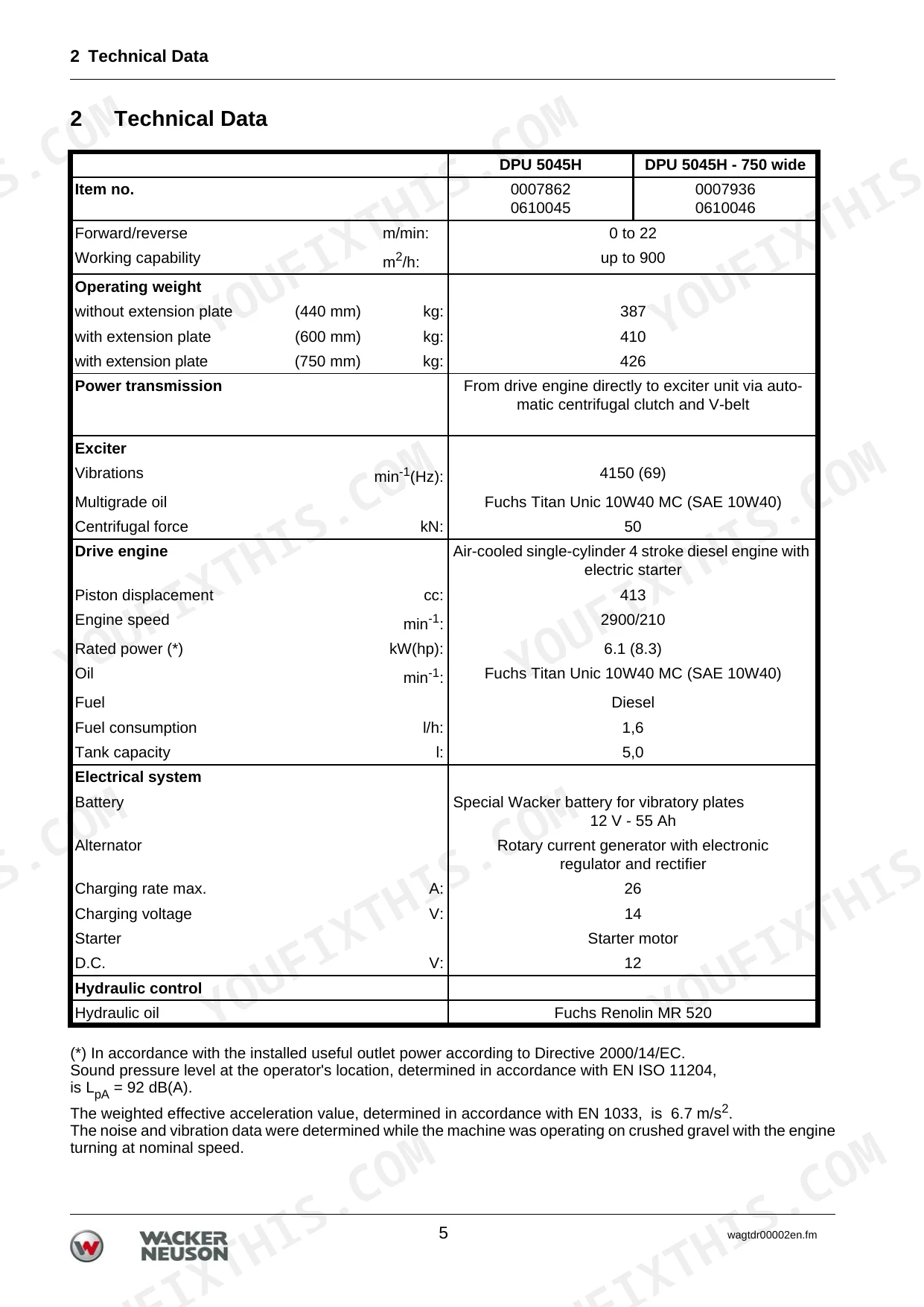
| Machine Identification & Specifications | 10-15 | Operating Weight, Power Transmission, Exciter, Drive Engine, Electrical System, Hydraulic Control, Applications, Description of Function |
| Operation | 16-21 | Starting Requirements, Switching Off, Compaction Without Extension Plates, Emergency Manual Starting, Mechanical Oil Pressure Control |
| Tools & Clutch/Cover Service | 22-49 | Press-Out Tool, Strap Wrench, Removing/Installing Side Covers and Battery, Disassembling Clutch and Replacing V-Belt, Assembling Clutch and Installing V-Belt, Removing Bowden Cable |
| Engine & Centre Pole Overhaul | 50-107 | Removing/Installing Diesel Engine, Removing/Installing Upper Mass, Removing/Installing Complete Centre Pole, Disassembling/Assembling Centre-Pole Head, Disassembling/Assembling Base Plate and Exciter, Removing/Installing Exciter Shafts |
| Switches, Wiring & Hydraulic Line | 108-121 | Removing/Installing Switches and Wiring Harness, Removing/Installing Hydraulic Line, Bleeding the Hydraulic Line |
| Version Changes | 122-127 | Version 101: EPA-Compliant Engine, Version 102: Modified Exciter, Version 103: Centre-Pole Latch Modification |
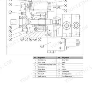
| Hav Drawbar Assembly | 128-161 | Center Pole Head, Control Piston, Gear Shaft, Compression Spring, Spacer, O-Ring, Pre-Assembly of the Drawbar, Assembly of the Dust Cover, Assembly of the Center Pole Support, Assembly of the Control, Pre-Assembly of the Bowden Cable, Assembly of the Bowden Cable in the Machine |
| Hav Drawbar Battery & Instrument Panel | 162-175 | Battery Guard, Jump Start Cables, Wiring Harness, Positive/Minus Pole Line, Cable Binder, Battery Cover, Housing, Coiled Helix Cable, Display Unit, Ignition Starter Switch, Operating Hour Meter |
| Hav Drawbar Disassembly | 176-191 | Center Pole Head, Control Piston, Compression Spring, Drawbar Pipe, Lock Coupling, Rubber-Metal Shockmount, Square Pipe, Vibration Damper, Battery Guard, Wiring Harness, Battery Cover, Ignition Starter Switch |
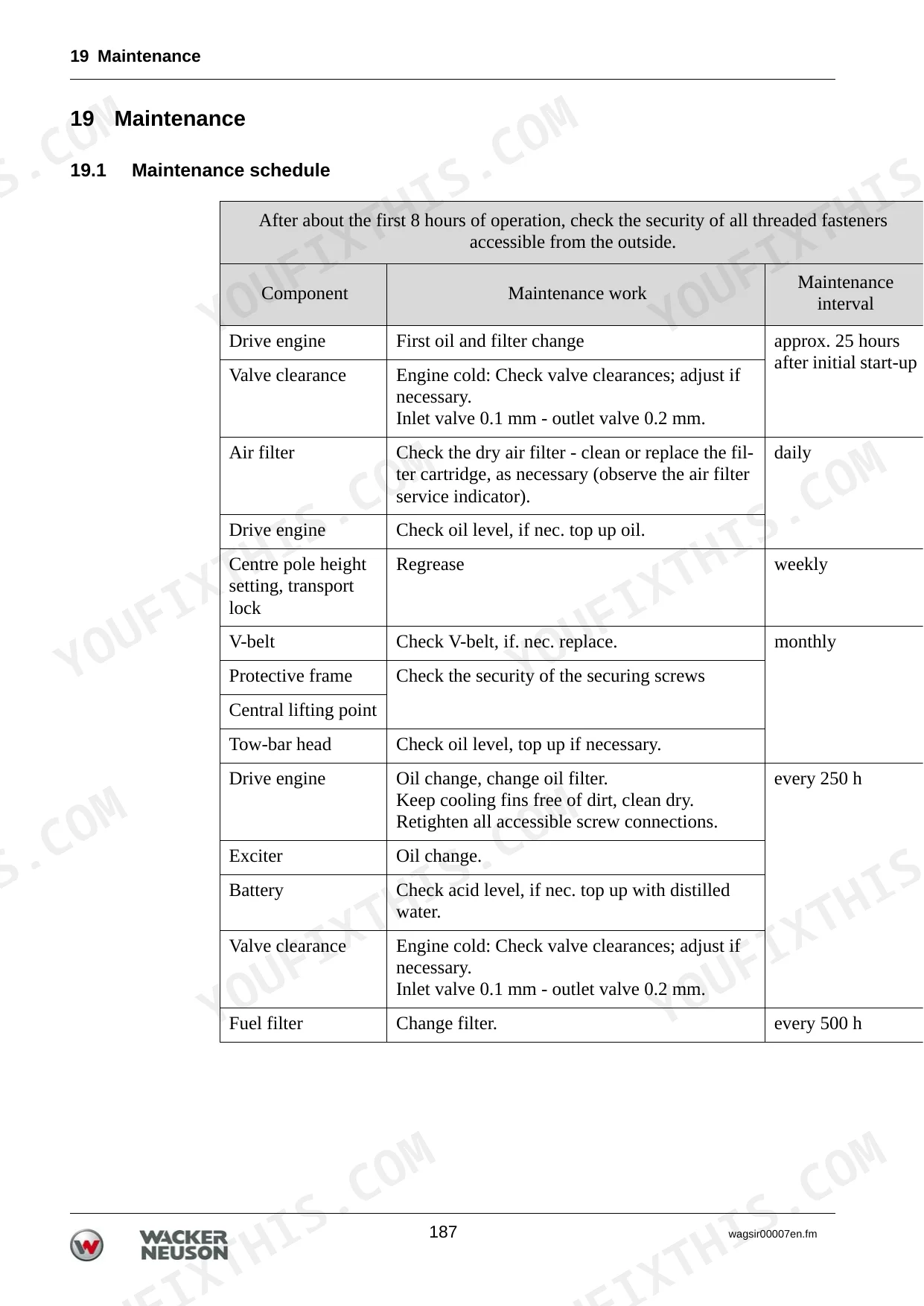
| Maintenance | 192-195 | Maintenance Schedule, Engine Oil, Battery, Hydraulic Control, Exciter, Check Oil Level, Exciter Vee-Belt |
| Troubleshooting | 196-197 | Forward Speed Too Low, Reverse Speed Too Low, No Reverse Motion, Loss of Hydraulic Oil, Charge Control Lamp Will Not Extinguish, Engine Does Not Start |
| Wiring Diagrams | 198-199 | Socket Plug, Starter Button, Wiring Harness, Indicator, Battery, Multifuse Overcurrent Switch |
| Tightening Torques | 200-202 | Metric Fasteners, Imperial Fasteners, Torque Values, Foot-Pounds, Newton-Meters |
Quick Reference Specifications
| Specification | Value | Page |
|---|---|---|
| Hydraulic Failure Remedy | Top up hydraulic oil, bleed system, replace defective parts if necessary, and correct oil level according to mark. | p. 196 |
| V-belt Replacement Criteria | Replace when width is less than 15.5 mm. | p. 42 |
| Bowden Cable Actuator Thread Projection | approx. 35 mm | p. 50 |
| Bowden Cable Adjuster Nut Position | rear nut to approx. 50 mm | p. 51 |
| Battery Voltage | 12 V | p. 10 |
| Battery Capacity | 55 Ah | p. 10 |
| Battery Buffer/Protector Replacement | Remove defective battery buffers (10) using a screwdriver and replace. | p. 28 |
| Rotary Shaft Seal Replacement (Exciter) | Remove if defective; can be used only once. Install with suitable tool and manual press, coat outside with oil. Pack space between dust excluder lip and sealing lip with Alvania R 2 grease. | p. 92 |
| Clutch Seal Replacement Criteria | Check at regular intervals and replace if necessary. | p. 43 |
Wacker Neuson DPU 5545, DPU 5045H, 5045H - 750 wide, 5045H - manual start Common Problems This Manual Covers
Plate will not vibrate
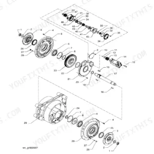
Weak or missing compaction usually traces to worn exciter bearings, damaged gears, or low oil in the exciter housing. The disassembly and assembly section covers exciter shaft removal, inspection, and reassembly.
Manual Section: 6 Disassembly / assembly p. 24Lost forward or reverse travel
Slow or missing travel in either direction can come from V-belt slip, hydraulic control problems, or a maladjusted Bowden cable. The faults section lists causes for low forward and reverse speed and no reverse motion.
Manual Section: 20 Faults p. 196Oil leaking from the exciter
Defective rotary shaft seals or damaged shaft surfaces let oil weep from the exciter housing. The disassembly and assembly section covers seal replacement and shaft inspection.
Manual Section: 6 Disassembly / assembly p. 24Worn V-belt or clutch slip
A stretched or worn V-belt makes the machine slow to drive the plate or hard to control. The disassembly and assembly section covers clutch teardown and V-belt replacement.
Manual Section: 6 Disassembly / assembly p. 24Overlooked exciter oil level
Skipping the exciter and engine oil checks is an easy way to cause early wear and failure. The maintenance section gives the service schedule and the oil level checks.
Manual Section: 19 Maintenance p. 192Engine will not start
Fuel delivery problems, air in the fuel system, or a discharged battery can stop the diesel from starting. The faults section covers no-start causes and the charge control lamp.
Manual Section: 20 Faults p. 196Frequently Asked Questions
Which models does this manual cover?
It covers the Wacker Neuson DPU 5545 and the DPU 5045H, including the DPU 5045H 750 wide and the DPU 5045H manual start versions.
Does it include tightening torque values?
Yes. The tightening torques section gives metric and imperial fastener values in newton metres and foot pounds for the machine. p. 200
Is there a wiring diagram?
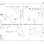
Yes. The wiring diagram section shows the starter button, wiring harness, indicator, battery, and the multifuse overcurrent switch. p. 198
Does it cover exciter repair?
Yes. The disassembly and assembly section covers exciter shaft removal, bearing and seal replacement, and reassembly with the correct press tools. p. 24
What format is this manual?
You get a 202-page searchable PDF that downloads instantly after checkout. Open it on your laptop, tablet, or phone and bring it right to the shop floor.
Am I able to print pages from this manual?
Yes. The PDF has no DRM restrictions, so you can print any page or section you need for your shop. Works with any standard printer.
Are there wiring harness diagrams in this Wacker Neuson DPU 5545, DPU 5045H?
Complete wiring diagrams are included, covering electrical circuits, harness routing, socket-plug connections, and the multifuse overcurrent switch for the Wacker Neuson DPU 5545, 5045H, 5045H - 750 wide, 5045H - manual start.

Reviews
There are no reviews yet.