


This is the factory repair manual for the Wacker RT 56-SC and RT 82-SC trench rollers, the remote-controlled articulated compactors powered by the Lombardini LDW 903 and LDW 1003 diesel engines. Publication 0160393en runs 184 pages and is written for the technician who already knows how to run the machine and now needs to troubleshoot or rebuild it.Inside you get technical data, periodic maintenance, engine starting troubleshooting flowcharts, and the full hydraulic system with manifold, valves, pressures and circuit schematics. Hydraulic troubleshooting walks through no vibration, no travel and no steering faults, while the disassembly and reassembly chapters cover the articulated joint, drive and slave hubs, exciter, steering cylinder and brake. The manual also documents the SmartControl transmitter, control box rebuild, threadlocker and sealant callouts, and metric and inch torque tables.Use it to fix no-start faults, service the hydraulics, and rebuild major components yourself.
What's Inside This Wacker RT 56-SC, RT 82-SC Repair Manual
| System | Pages | Key Topics |
|---|---|---|
| Safety Information | - | Laws Pertaining to Spark Arresters, Operating Safety, Operator Safety While Using Internal Combustion Engines, Service Safety, Warning and Informational Labels |
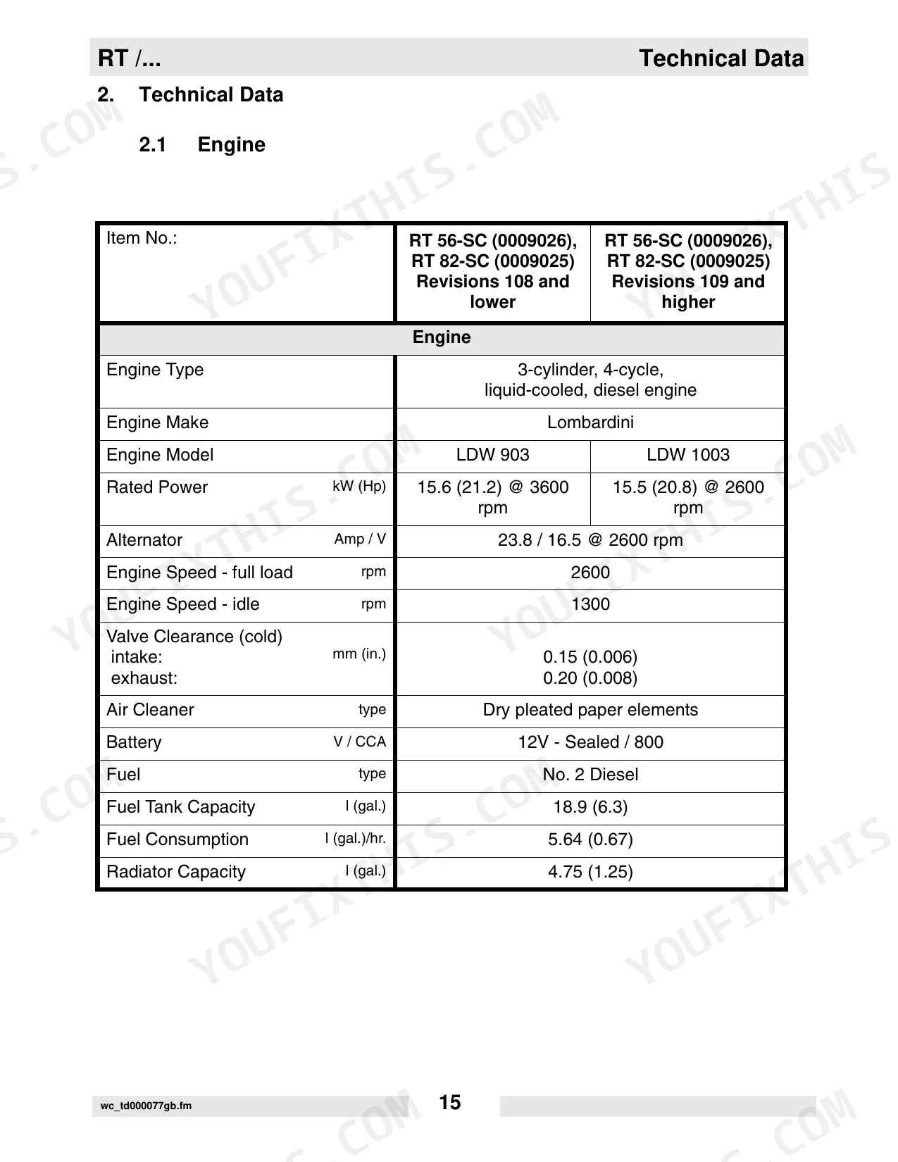
| Technical Data | - | Engine Specifications, Roller Specifications, Lubrication Requirements, Sound and Vibration Measurements, Machine Dimensions |
| Operation | - | Operation and Service Locations, Control Panel Features, SmartControl™ Transmitter, Infra-Red System and Control Channels, Starting and Stopping Procedures |
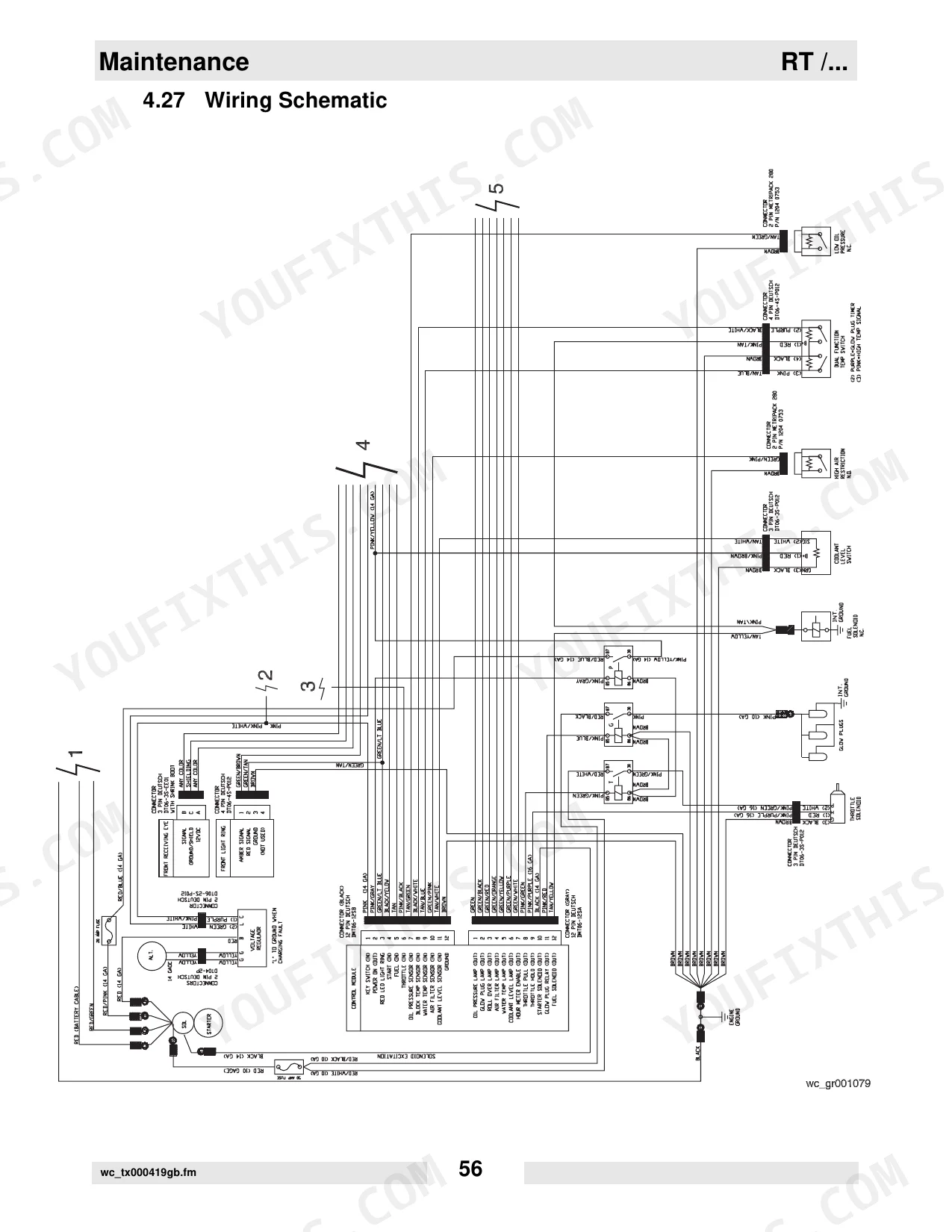
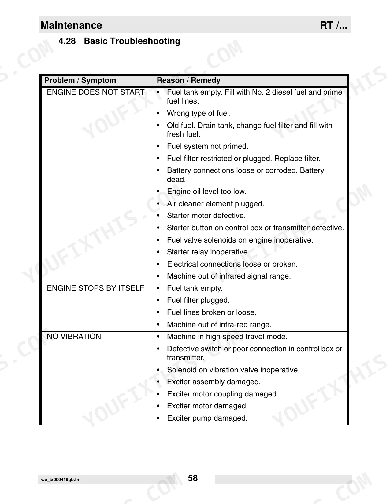
| Maintenance | - | Periodic Maintenance Schedules, Hydraulic Oil Requirements, Engine Oil System, Air Cleaner, Fuel Filter, Valve Clearances, Wiring Schematic, Basic Troubleshooting |
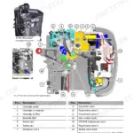
| Engine Starting Troubleshooting | - | Component Locations, Troubleshooting Flowcharts, Checking 20A Fuse, Checking Receiving Eyes, Replacing Keyswitch, Testing Ecm, Checking Fuel Solenoid, Checking Glow Plugs |
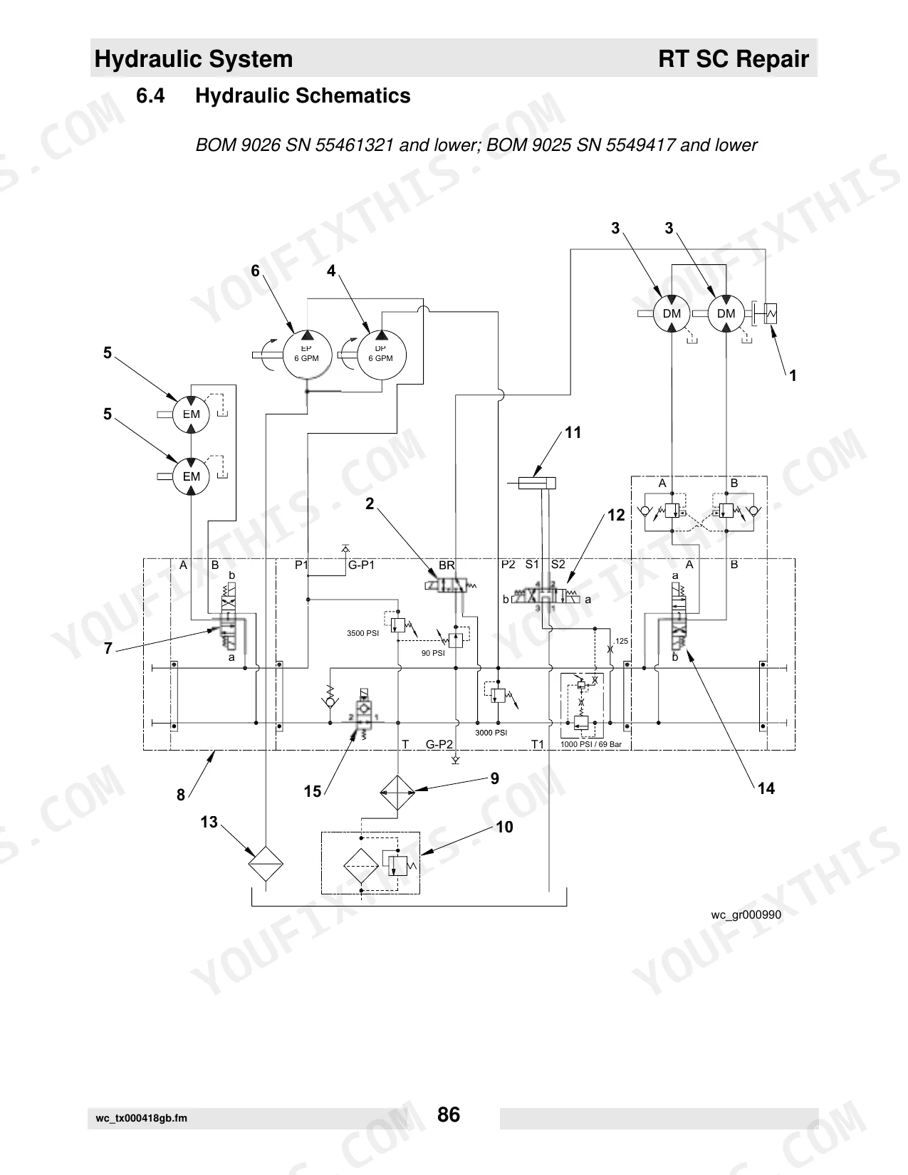
| Hydraulic System | - | Hydraulic Manifold, Hydraulic Valves, Hydraulic System Pressures, Hydraulic Schematics, Exciter Circuit, Drive and Brake Circuit, Steering Circuit |
| Hydraulic Troubleshooting | - | No Vibration Flowchart, Checking Decoder Module, Replacing Solenoid, Checking Exciter Motors, No Steering Flowchart, No Travel Flowchart, Checking Function of Brake |
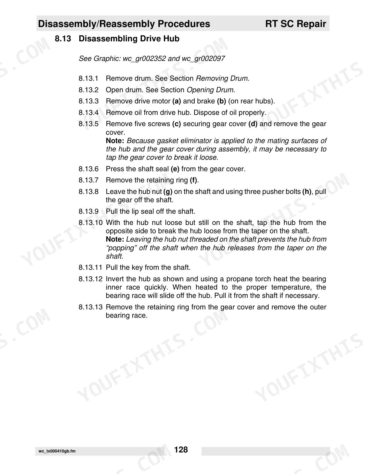
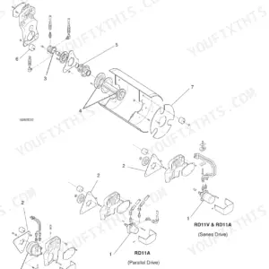
| Disassembly/Reassembly Procedures | - | Articulated Joint, Drum Support, Drive Hub, Slave Hub, Rebuilding Brake, Exciter, Steering Cylinder, Valve Block |
| Rebuilding Control Box | - | Removing/Rebuilding Joysticks, Removing and Installing Circuit Boards, Removing & Testing Control Button Circuit Board |
| Threadlockers and Sealants | - | Loctite 222, Loctite 243, Loctite 271/277, Loctite 290, Loctite 609, Loctite 545, Loctite 592, Loctite 515 |
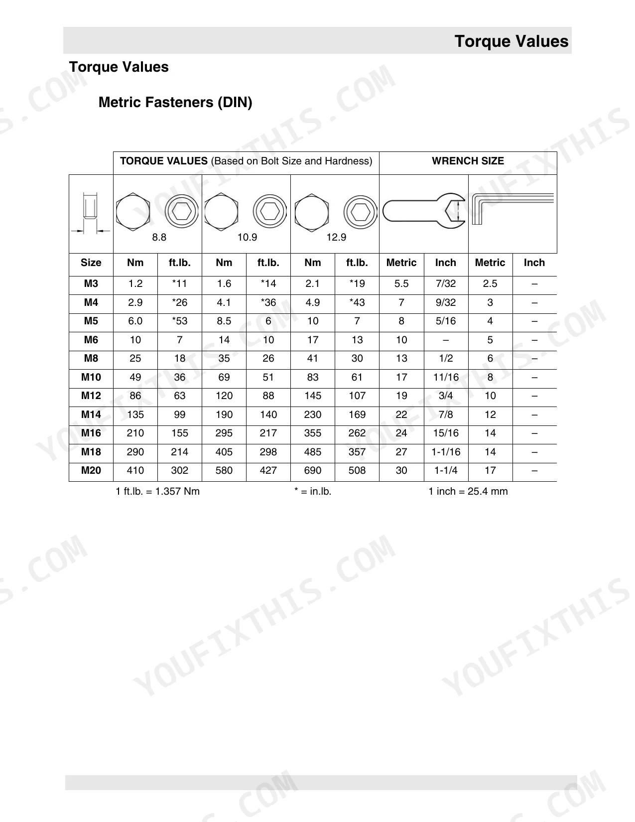
| Torque Values | - | Metric Fasteners (Din) Table, Inch Fasteners (Sae) Table |
Quick Reference Specifications
| Specification | Value | Page |
|---|---|---|
| Metric Fasteners (DIN) Torque Values (8.8 hardness) | M3: 1.2 Nm, M4: 2.9 Nm, M5: 6.0 Nm, M6: 10 Nm, M8: 25 Nm, M10: 49 Nm, M12: 86 Nm, M14: 135 Nm, M16: 210 Nm, M18: 290 Nm, M20: 410 Nm | p. 181 |
| Metric Fasteners (DIN) Torque Values (10.9 hardness) | M3: 1.6 Nm, M4: 4.1 Nm, M5: 8.5 Nm, M6: 14 Nm, M8: 35 Nm, M10: 69 Nm, M12: 120 Nm, M14: 190 Nm, M16: 295 Nm, M18: 405 Nm, M20: 580 Nm | p. 181 |
| Metric Fasteners (DIN) Torque Values (12.9 hardness) | M3: 2.1 Nm, M4: 4.9 Nm, M5: 10 Nm, M6: 17 Nm, M8: 41 Nm, M10: 83 Nm, M12: 145 Nm, M14: 230 Nm, M16: 355 Nm, M18: 485 Nm, M20: 690 Nm | p. 181 |
| Inch Fasteners (SAE) Torque Values (SAE 5) | No.4: 0.7 Nm, No.6: 1.4 Nm, No.8: 2.5 Nm, No.10: 3.6 Nm, 1/4: 8.1 Nm, 5/16: 18 Nm, 3/8: 31 Nm, 7/16: 50 Nm, 1/2: 77 Nm, 9/16: 111 Nm, 5/8: 152 Nm, 3/4: 271 Nm | p. 182 |
| Hydraulic system return line filter replacement interval (New Machines) | after first month or 100 hours | p. 42 |
| Hydraulic system return line filter replacement interval (Periodic Maintenance) | Once A Year | p. 43 |
| Engine oil filter replacement interval (New Machines) | after first 50 hours | p. 42 |
| Engine oil filter replacement interval (Periodic Maintenance) | Every 125 hrs. | p. 43 |
| Air filter element replacement condition | if indicator light is on | p. 43 |
| Engine fuel filter replacement interval | every 300 hours of operation | p. 51 |
| Fuel filter cartridge replacement interval (Periodic Maintenance) | Every 250 hrs. | p. 43 |
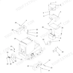
| Main battery voltage | 12V | p. 19 |
Wacker RT 56-SC, RT 82-SC Common Problems This Manual Covers
Hard or intermittent starting
Owners often hit no-start or intermittent start after the machine sits, usually from stale fuel, an empty or unprimed fuel system, a restricted fuel filter, or weak battery connections. The engine starting troubleshooting flowcharts isolate the cause step by step.
Manual Section: Engine Starting TroubleshootingHydraulic oil level keeps dropping
If the machine repeatedly needs hydraulic oil topped off, hoses and connections are usually leaking and should be inspected and repaired before hydraulic components are damaged.
Manual Section: Hydraulic SystemNo vibration, travel, or steering
Loss of vibration, drive, or steering is a common field complaint on these rollers. The hydraulic troubleshooting flowcharts cover the decoder module, solenoids, exciter motors and brake function to find the fault.
Manual Section: Hydraulic TroubleshootingEngine loses fuel prime
After service or a dry start the fuel system can lose prime and need bleeding. Routine fuel filter changes and the priming procedure in the maintenance section restore reliable starting.
Manual Section: MaintenanceErratic control or transmitter faults
Intermittent operation often traces to the SmartControl transmitter or control box, where contamination, worn joysticks or a failing circuit board disrupt the infra-red signal. The control box rebuild section covers testing and replacement.
Manual Section: Rebuilding Control BoxWear in hubs, exciter, or joints
Neglected greasing and hard use wear the articulated joint, drive and slave hubs, exciter and steering cylinder. The disassembly and reassembly procedures show how to rebuild each one.
Manual Section: Disassembly/Reassembly ProceduresFrequently Asked Questions
Which machines does this repair manual cover?
It covers the Wacker RT 56-SC and RT 82-SC trench rollers built around the Lombardini LDW 903 and LDW 1003 diesel engines, factory publication 0160393en.
Where are the torque specifications?
The Torque Values section provides metric (DIN) and inch (SAE) fastener tables. The metric grade 8.8 through 12.9 values are on page 181, with the SAE tables on the following page. p. 181
How often should the hydraulic return filter be changed?
Under periodic maintenance the hydraulic return line filter is replaced once a year, and on new machines after the first month or 100 hours. The filter removes particles down to 10 microns. p. 43
How do I diagnose a machine that will not start?
The engine starting troubleshooting section provides flowcharts that check the 20A fuse, receiving eyes, keyswitch, fuel solenoid, glow plugs and ECM in sequence so you can isolate a no-start without guesswork.
What do I get after purchasing this Wacker RT 56-SC, 82-SC manual?
After checkout, the 184-page searchable PDF downloads instantly. Open it on a laptop, tablet, or phone and bring it right to the shop floor.
Can I print specific sections of this Wacker RT 56-SC, 82-SC Repair Manual?
Yes. The PDF carries no DRM restrictions, so you can print any page or section you need on a standard printer.
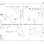
Can I find wiring schematics in this Wacker RT 56-SC, 82-SC manual?
Yes. You'll find full electrical schematics with wire routing diagrams, connector identification, and circuit descriptions.


Reviews
There are no reviews yet.