


Part of the Yanmar Repair Manuals.
Need the factory operation data for your Yanmar 6N18(A)L-V marine propulsion engine? This 353-page Yanmar 6N18(A)L-V operation manual PDF (OEM #06-6N18(A)VH-220) covers the full 6N18L family: DV, UV, SV, EV, and AL-HV variants. Inside: engine system diagrams mapping every fluid circuit and device arrangement, routine maintenance schedules with step-by-step adjusting procedures, full servicing procedures for cylinder head, pistons, connecting rods, main bearings, and timing gear, plus clearances and wear limits for every major component. You also get a troubleshooting section, a major-bolt torque table, and an illustrated parts list covering cylinder head through lubrication assemblies. Set nozzle sleeve torque to 157~167 N-m running MDO, or 245~265 N-m on HFO, then confirm injection pressure holds at 34.0 ± 0.5 MPa. Your vessel doesn't wait for shore support. Bookmarked by section; search any spec by keyword and get back to the engine room.
What's Inside This Yanmar 6N18(A)L-V Manual
| System | Pages | Key Topics |
|---|---|---|
| Preface | 3-20 | Foreword, Terms & Symbol Marks |
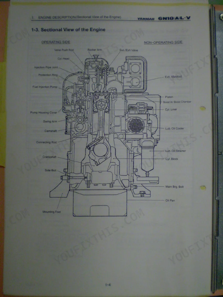
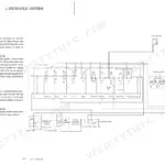
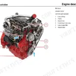
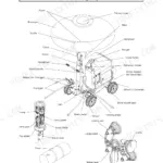
| Engine Description | 21-26 | Engine Specification, Types of Accessories & Attachments, Sectional View of the Engine, Engine Outline & Device Arrangement |
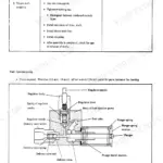
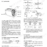
| Structure of Major Parts | 27-32 | Cylinder Block, Cylinder Liner, Cylinder Head, Piston and Piston Rings, Connecting Rod, Fuel Injection Pump |
| Table of Engine Standard Adjustments | 33-35 | Assembly Adjustment Values, Pressure & Temperature Setting Values, Protective Device Setting Values, Holding Volumes of Lubricating Oil and Cooling Water |
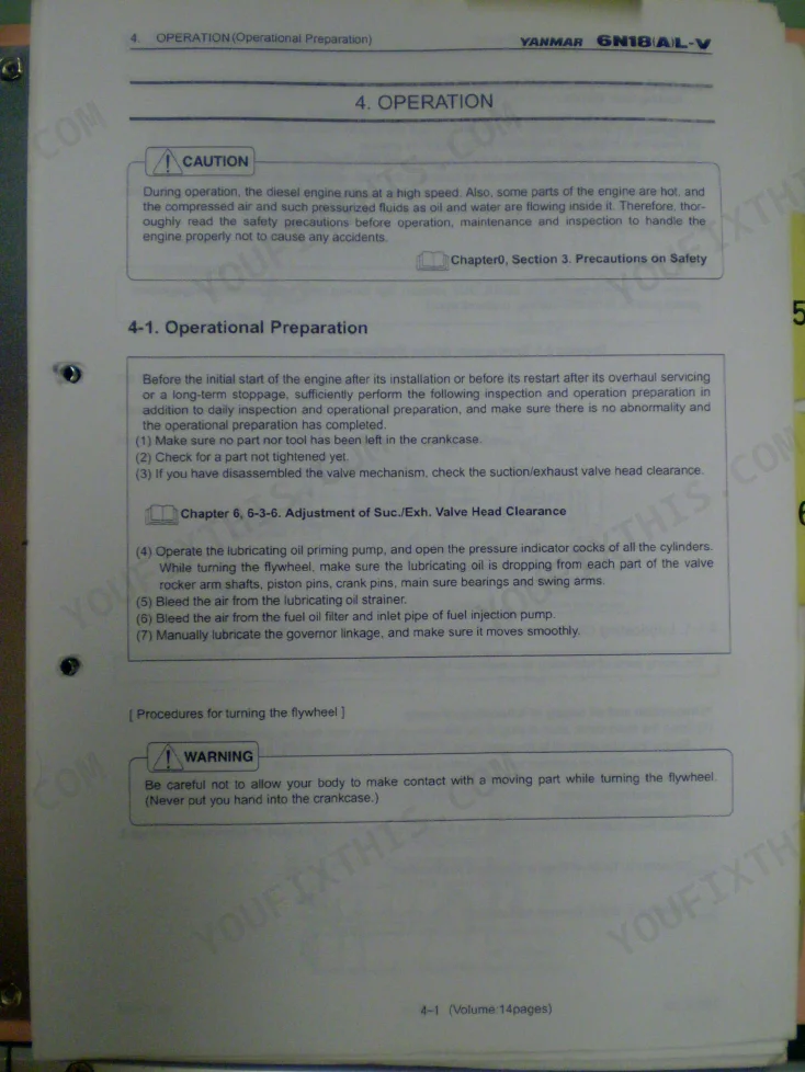
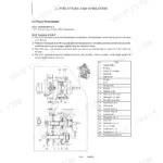
| Operation | 36-50 | Operational Preparation, Starting, Running, Stopping |
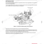
| Fuel Oil, Lub. Oil & Cooling Water | 51-62 | Fuel Oil, Lubricating Oil, Cooling Water (Engine Jacket Water) |
| Maintenance Checking | 63-103 | Precautions in Maintenance Checking, Routine Maintenance Checking & Adjusting Procedures |
| Maintenance Servicing | 104-163 | Precautions in Maintenance Servicing, Cylinder Head & Its Accessories, Piston & Connecting Rod, Cylinder Block & Cylinder Liner, Main Bearing & Crankshaft, Timing Gear |
| Principal Dimensions & Part Mass for Disassembly & Servicing | 164-166 | Cylinder Head Mass, Piston & Connecting Rod Assy. Mass, Cylinder Liner Mass, Air Cooler Mass, Crankshaft Mass, Flywheel Mass |
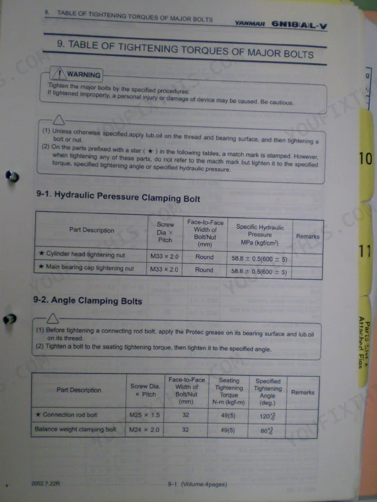
| Table of Tightening Torques of Major Bolts | 167-170 | Hydraulic Pressure Clamping Bolt, Angle Clamping Bolts, Other Major Bolts (Torque Tightening), Indicator Cock Tightening Nut, Rocker Arm Shaft Stand Clamping Bolt |
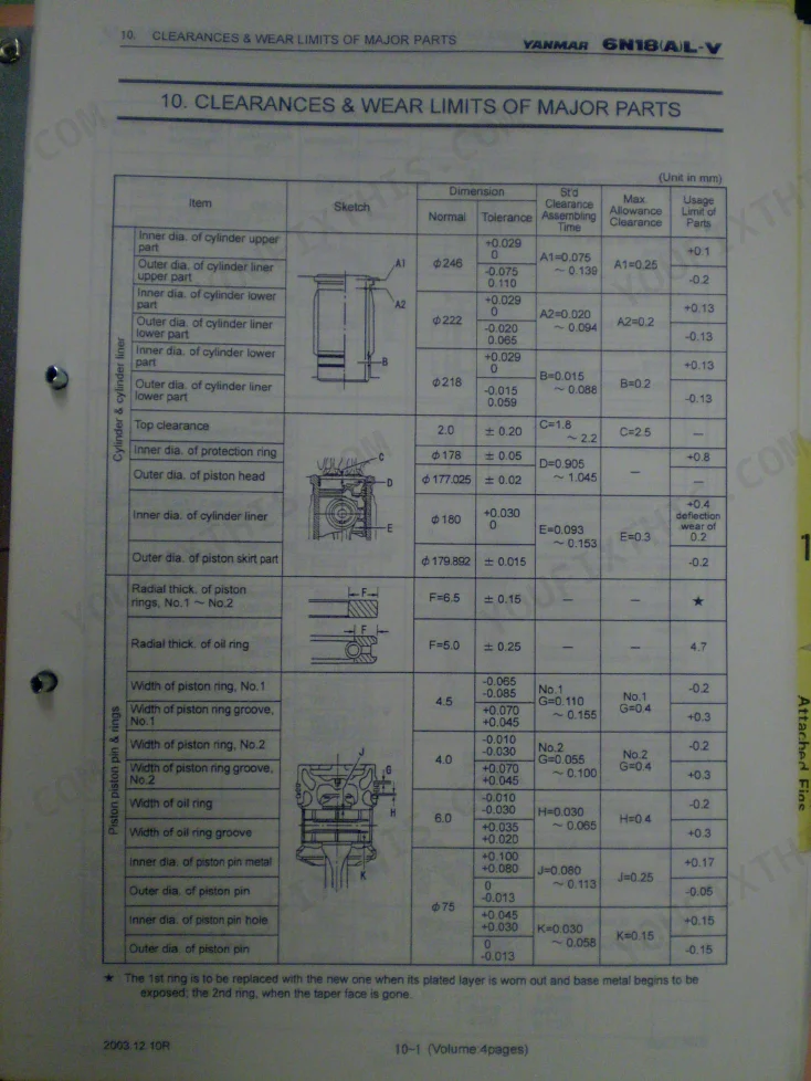
| Clearances & Wear Limits of Major Parts | 171-174 | Cylinder & Cylinder Liner, Piston Piston Pin & Rings, Crankshaft, Lub. Oil Pump, Cooling Water Pump, Fuel Oil Feed Pump |
| Troubleshooting & Countermeasures | 175-180 | Starting Failure, Rotational Speed Dropped Spontaneously, Bad Color of Exhaust Gas, Lub. Oil Pressure Dropped Below the Specified Pressure |
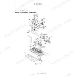
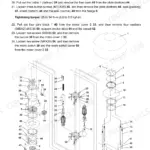
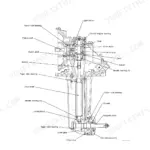
| Fig 1. Cylinder Head Ass'y | 186-191 | Cylinder Head Parts, Valve & Seat Components, Injector Nozzle Holder Assembly |
| Fig 3. Indicator Cock Ass'y | 192-194 | Valve Rotator Parts, Indicator Cock Components, Spring & Sealing Elements |
| Fig 5-1. Cylinder Block Side Cover Ass'y | 195-196 | Valve Mechanism Parts, Side Cover Gaskets, Mounting Bolts & Hardware |
| Fig 5-2. Cylinder Block Side Cover Ass'y, with Lub. Oil Filler | 197 | Lubricating Oil Filler Cap, Side Cover Components, Filler Seals & Gaskets |
| Fig 5-3. Cylinder Block Side Cover Ass'y, with Safety Valve | 198 | Safety Valve Assembly, Spring-Loaded Relief Valve, Side Cover Sealing Elements |
| Fig 6. Cylinder Liner Ass'y | 199 | Cylinder Liner Parts, O-Ring Seals, Liner Cooling Jacket Components |
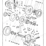
| Fig 7. Main Bearing Ass'y | 200-201 | Main Bearing Shells, Bearing Caps, Bearing Retaining Bolts |
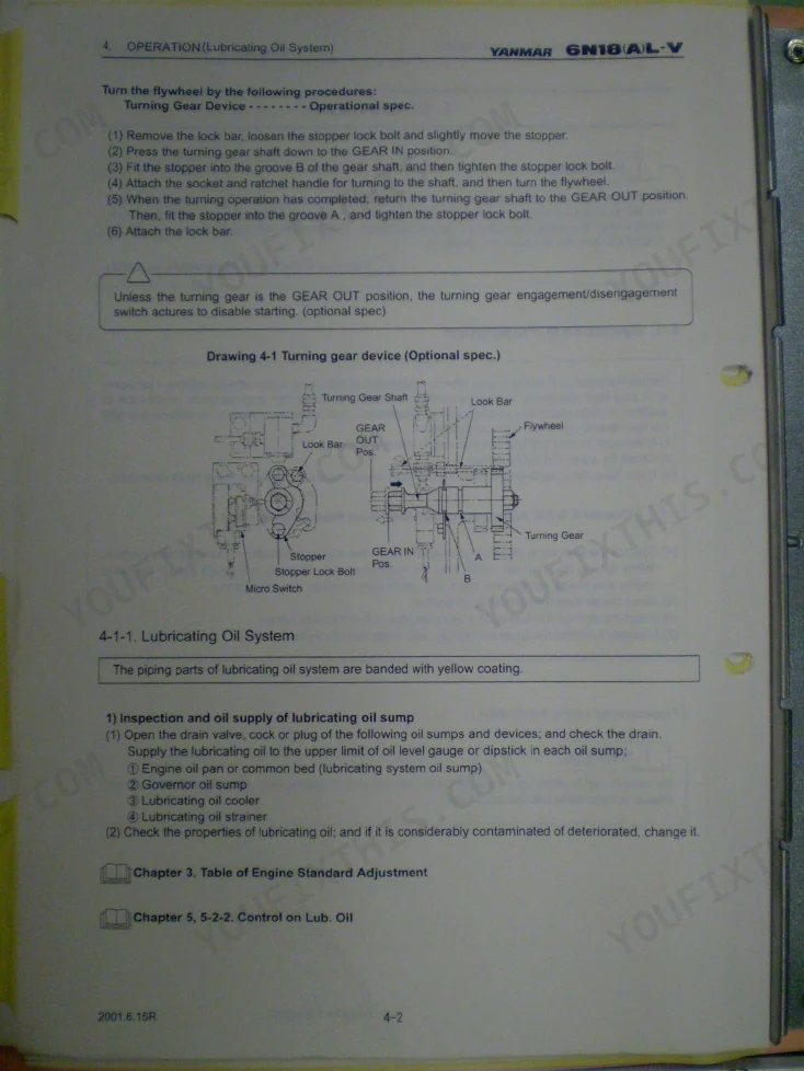
| Fig 8. Turning Device | 202-353 | Turning Gear Assembly, Turning Device Components, Engagement Mechanism |
Quick Reference Specifications
| Specification | Value | Page |
|---|---|---|
| Cylinder head tightening nut torque | 58.8 ± 0.5 MPa (600 ± 5 kgf/cm²) | p. 167 |
| Fuel injection valve nozzle sleeve torque (Engine Using MDO) | 157~167 N-m (16~17 kgf-m) | p. 168 |
| Fuel injection valve nozzle sleeve torque (Engine Using HFO) | 245~265 N-m (25~26 kgf-m) | p. 168 |
| Nozzle average service life | 2,500 hours | p. 78 |
| Exhaust manifold clamping bolt torque | 59~69 N-m (6~7 kgf-m) | p. 168 |
| Exhaust expansion joint clamping bolt torque | 59~69 N-m (6~7 kgf-m) | p. 168 |
| Main bearing cap side bolt torque | 343~382 N-m (35~39 kgf-m) | p. 168 |
| Lub. oil strainer overhaul cleaning interval | 10~15 days | p. 64 |
| Turbocharger lubricating oil strainer element replacement criterion (pressure drop) | 0.3 MPa (3 kgf/cm²) | p. 92 |
| Cooling fresh water pH | 6.3~8.0 | p. 60 |
| Cooling fresh water total hardness (CaCO3) | < 100 ppm | p. 60 |
| Piston top clearance | 2.0 ± 0.2 mm | p. 33 |
Yanmar 6N18(A)L-V Common Problems This Manual Covers
Yanmar 6N18(A)L-V flywheel turns but engine won't fire or fires intermittently
Drain the fuel separator and replace fuel filters to clear water or algae contamination. Bleed all air from the system completely. Verify injection valve opening pressure is 34.0 ± 0.5 MPa (347 ± 5 kgf/cm²) per the standard adjustments on page 33. Work through the starting failure diagnosis in Troubleshooting & Countermeasures starting at page 176.
Manual Section: Troubleshooting & Countermeasures p. 176Cooling water temperature rising above normal operating range, high-temperature alarm triggering repeatedly
Inspect the thermostatic valve element for sticking or defect; correct lift in water of 30°C or less is 5 ± 0.1 mm (page 83). Verify jacket water quality meets specifications on page 60: pH must be 6.3~8.0 and chlorine ions below 100 ppm. Replace anticorrosive zinc once consumed more than 70% of original volume (page 102).
Manual Section: Maintenance Checking p. 83Engine runs rough with uneven cylinder output and visible black exhaust smoke
Remove each fuel injection valve and bench-test opening pressure against the spec of 34.0 ± 0.5 MPa (page 33). Nozzle service life averages 2,500 hours (page 78), so replace overdue valves. On MDO engines, torque the nozzle sleeve to 157~167 N-m (page 168). Check injection timing and cam condition if output imbalance persists after valve replacement.
Manual Section: Maintenance Checking p. 78Lubricating oil pressure alarm activates during operation, pressure falling below specified range
Overhaul and clean the lub. oil strainer every 10~15 days as scheduled on page 64. Inspect the FM200 centrifugal bypass filter rotor; clean when internal dirt deposit exceeds 35 mm (page 89). Replace turbocharger strainer elements if outlet pressure falls to 0.3 MPa (3 kgf/cm²) as specified on page 92. Verify oil level is correct and not aerated.
Manual Section: Maintenance Checking p. 64Persistent knocking or abnormal metallic sounds heard during normal engine operation underway
Verify fuel injection timing and valve clearances against the standard adjustment values on page 33. Measure main bearing and crankshaft clearances against wear limits starting at page 171. Check that key fasteners meet torque spec; M10 × 1.5 bolts take 44~54 N-m (page 169). Isolate each cylinder in turn to pinpoint whether the knock is combustion or mechanical.
Manual Section: Clearances & Wear Limits of Major Parts p. 171Engine shuts down unexpectedly at sea, no prior alarm or warning received
Check the fuel tank level immediately, then inspect fuel oil filters for clogging. Bleed air from the fuel system and verify governor response. Review protective device setting values on page 33 to confirm alarm setpoints are correct. Follow the Engine Stopped Suddenly countermeasures in Troubleshooting & Countermeasures from page 175 before attempting restart.
Manual Section: Troubleshooting & Countermeasures p. 175Frequently Asked Questions
How to start YANMAR 6N18(A)L-V after shutdown?
To start the engine, first ensure the turning gear is in the GEAR OUT position and the pressure indicator cock is closed. Set the ENGINE/REMOTE operation selector switch and the start/stop lever in the RUN position. Confirm the governor's speed control shaft indicates ordinary operation (rated speed), then open the starting air reservoir and control air valves. Hold the START switch for 2 to 3 seconds until ignition is confirmed, then release. p. 43
What do I get after purchasing this Yanmar 6N18(A)L-V manual?
A 353-page Operation Manual in searchable PDF format (142 MB), available the moment you complete checkout. View on computer, tablet, or phone, with no shipping wait.
Can I print this Yanmar 6N18(A)L-V manual?
Zero restrictions. The PDF is DRM-free. Print whatever sections you need to take out to the shop. Standard letter or A4 paper works.
Reviews
There are no reviews yet.