


Part of the Yanmar Repair Manuals.
Need factory-level depth on your Yanmar V70S wheel loader? This 766-page service manual (OEM #02) is the factory reference for the V70S, covering TCD 2.9 L4 Tier 4 diesel workshop procedures, full travel hydraulics, and complete electrical systems. You get hydraulic circuit diagrams for the standard layout and optional circuits, displacement pump A4VG045DA1 and motor A6VM DA1 setting procedures, plus the electrical section with cable color charts, fuse and relay assignments, and pinout diagrams. A full diagnostics chapter rounds it out: ACTIA messaging specs, dashboard error codes for both software variants, and SerDia 2010 SPN/FMI fault codes. Set your main relief valve to 250+5 bar at high idle; torque the lubricating oil filter to 10-12 Nm. No more chasing fault codes through forum threads. Grab your tablet, open the bookmarked sections, and get back to work.
What's Inside This Yanmar V70S Manual
| System | Pages | Key Topics |
|---|---|---|
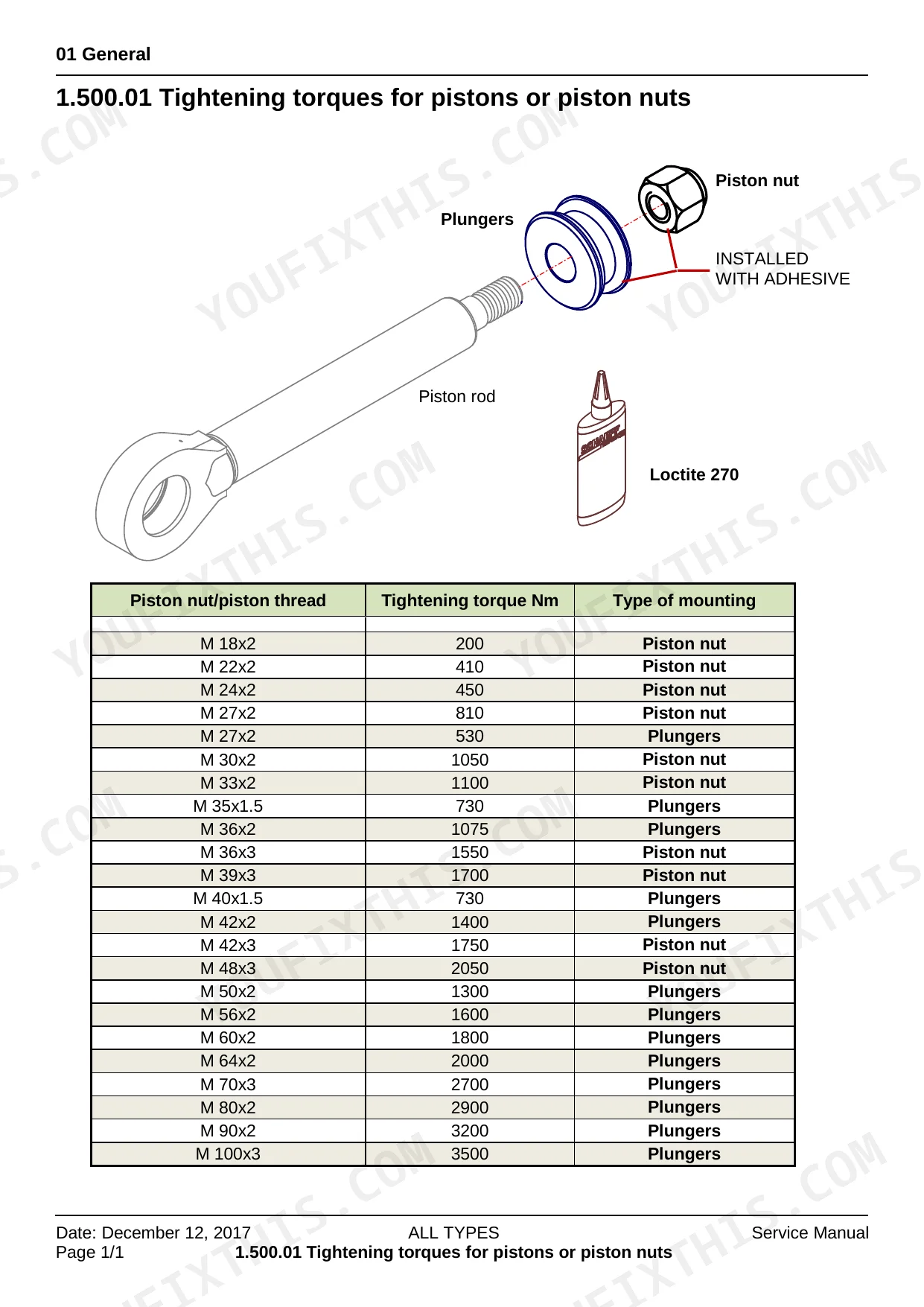
| General | 3-46 | Introduction / User Notice, Safety and Accident Prevention, Symbol and Hazard Descriptions, Tightening Torques for Pistons or Piston Nuts, Tightening Torques for Guide Bushings |
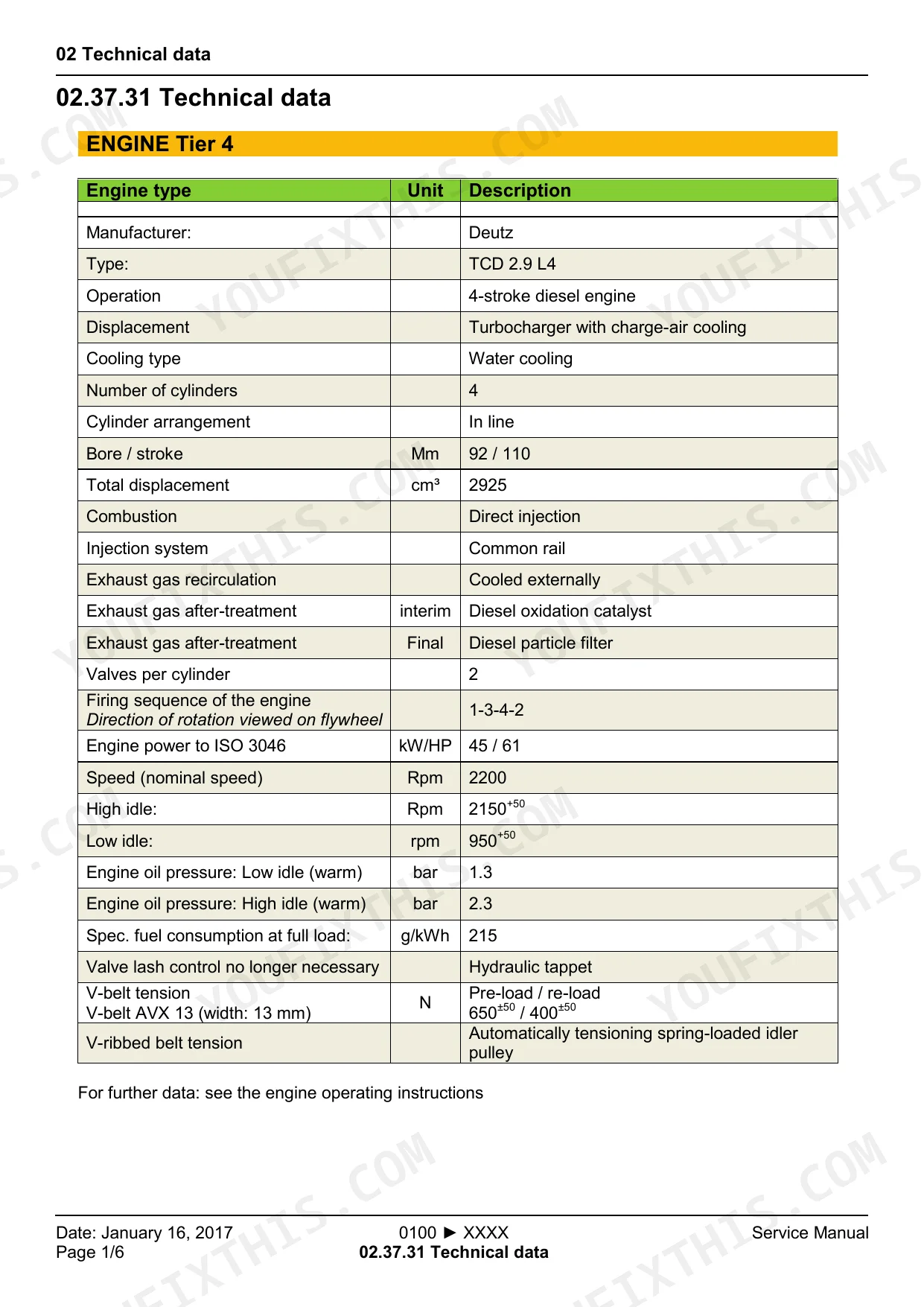
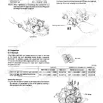
| Technical Data | 47-56 | Drift Values |
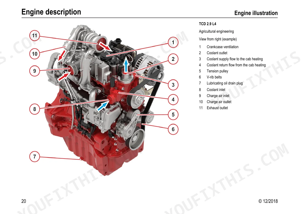
| Diesel Engine | 57-368 | Operating Manual D_TD_TCD 2.9 L4 – 12_2018, Workshop Manual Tcd 2.9 L4Tier 4 - 2018_06, Bleeding the Fuel System |
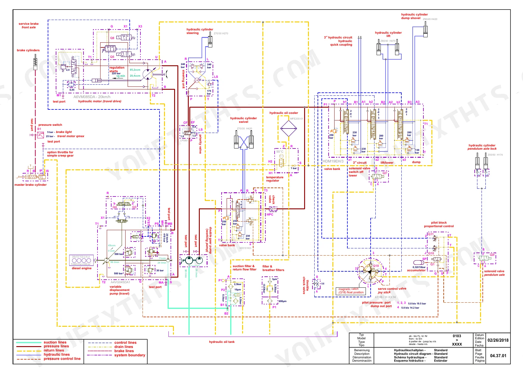
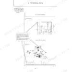
| Hydraulics | 369-372 | Hydraulic Circuit Diagram - Standard, Hydraulic Circuit Diagram - Additional Circuit and Options |
| Setting Instructions | 373-398 | Hydromatik Tightening Values, Valve Description - HDM19WL, Displacement Pump - A4VG045DA1, Displacement Motor – A6VM DA1, Travel Hydraulics – Setting Instructions |
| Functional Description | 399-402 | Pilot Control Device 4TH6 with Handle Options |
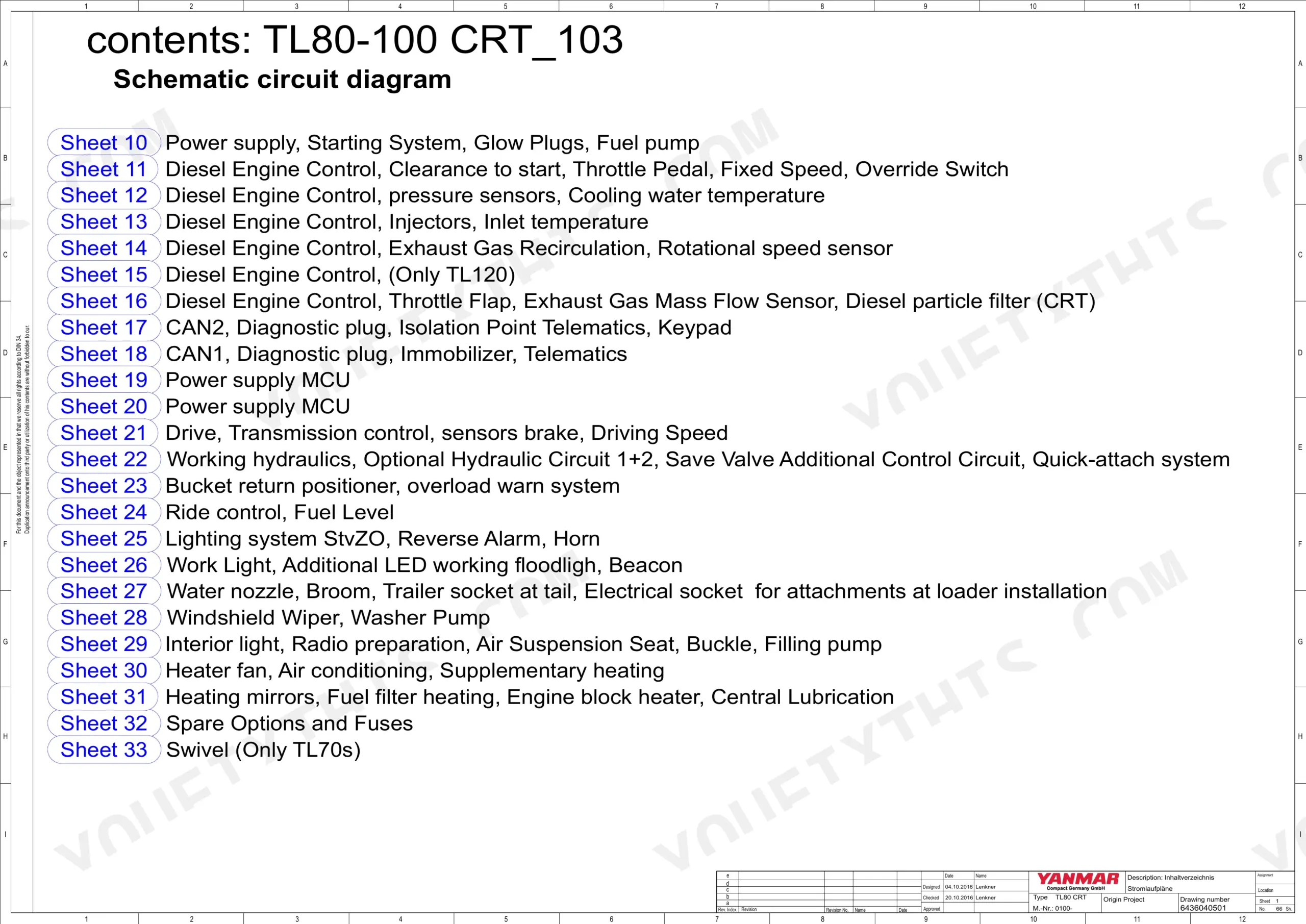
| Electrics | 403-552 | Cable Colors Overview, Vehicle Electrics - Project: TL80-100 CRT_103.pdf, Vehicle Electrics - Project: TL80-100 DOC_103.pdf, Fuse Assignment, Relay Assignment |
| Maintenance | 553-562 | Specification for Fuels, Lubricants, And Coolants, Inspection Plan |
| Operation | 563-630 | Keypad Operation, Instructions for Using the Combo-Tool |
| Options | 631-640 | Exhaust Gas After-Treatment System – Diesel Particle Filter Replacement |
| Repair Instructions | 641-664 | Fitting Hydraulic Screw Connections, Adhesive Kit – Cab Windows, Ride Control System - "Lsd" |
| Diagnostics / Tools | 665-766 | Special Tools - Purchased Parts, Actia - Diagnostic Messaging Specification, Error Codes: Dashboard - Software Variants, SerDia 2010 - Diagnoses- and Error Codes Spn / Fmi |
Quick Reference Specifications
| Specification | Value | Page |
|---|---|---|
| Main relief valve (high idle) set point | 250+5 bar | p. 52 |
| Daily operating hours counter reset value | 0.0 hours (h) | p. 629 |
| Tightening torque for DKO hose (L6 M12 x 1.5 to L42 M52 x 2.0) | 18 Nm to 380 Nm ± 5% | p. 652 |
| Lubricating oil filter tightening torque | 10 Nm - 12 Nm | p. 124 |
| Minimum straight pipe end dimension for hydraulic screw connections | > double the nut height | p. 647 |
| Permissible continuous coolant temperature | max. 110 °C | p. 151 |
| Engine power to ISO 3046 | 45 / 61 kW/HP | p. 49 |
| Main relief valve (working hydraulics, high idle) | max. 250+5 bar | p. 52 |
| M12 seal-lock sealing nut tightening torque | 69 Nm | p. 378 |
| Lubricating oil drain plug tightening torque | 10 Nm - 12 Nm | p. 124 |
| DPF regeneration duration | 35-40 minutes | p. 639 |
| Piston pressure accumulator (gas side) fill pressure | approx. 20 bar | p. 663 |
Yanmar V70S Common Problems This Manual Covers
Yanmar V70S hydraulic hoses seeping at quick disconnect block or control lever fittings, bucket lift weak and erratic
Inspect every connection at the quick disconnect blocks and control levers for seepage. The straight pipe end must extend more than double the nut height before threading (page 647). Tighten DKO fittings to spec: M12 starts at 18 Nm, M52 x 2.0 requires up to 380 Nm, all within ±5% (page 652). Replace any hose showing cracks or braid separation.
Manual Section: Hydraulic System Leaks (Causes and Prevention) p. 647Engine coolant temperature climbs past normal, overheating warning activates during heavy lift cycles
Shut down and let the engine cool before touching the cooling system. Clear debris from the radiator fan passages before each shift. Continuous coolant temperature must stay below 110°C (page 151); anything above that warrants immediate shutdown and inspection. Check all hose connections and clamp tightness. For a full list of overheating corrective measures, start at the troubleshooting procedures.
Manual Section: Engine Faults and Corrective Measures (General)Transmission level indicator reads below the green zone, machine hesitates or won't pull under load
Lower the bucket fully and shut the engine off before checking the transmission oil level. Verify the fill volume against the fluid capacities table on page 54. Inspect travel motor connections and case drain fittings for external leaks. If drive response stays poor with the level correct, confirm working hydraulic pressure reaches 250+5 bar at high idle (page 52).
Manual Section: Maintenance p. 54Hydraulic functions sluggish or spongy after hose replacement, boom travel feels inconsistent
Cycle the boom and bucket through full range at least five times after hose replacement, then recheck the hydraulic oil level; trapped air reads as false-low until purged. Verify all DKO fitting torques: M12 starts at 18 Nm, large-bore M52 x 2.0 lines require up to 380 Nm ±5% (page 652). Check quick disconnect blocks for seepage after the first work cycle.
Manual Section: Repair Instructions p. 652DPF warning stays lit on the dash and engine drops into power reduction mode during operation
Keep the engine running at operating load when the DPF warning activates. Allow the forced regeneration cycle to finish: it takes 35 to 40 minutes (page 639). If you must stop, restart and resume the cycle as soon as possible; each aborted cycle increases ash load in the filter. For warning strategies and power reduction sequences, see the aftertreatment section starting at page 631.
Manual Section: Exhaust Gas Aftertreatment System Diagnostics and Repair p. 639Frequently Asked Questions
How to reset Yanmar V70S error codes?
To reset error codes, ensure all errors are rectified. For some errors, it is necessary to switch off the ignition, wait 30 seconds, and then switch back on the ignition. The diagnostics lamp will go out once all errors are cleared. p. 144
What are the torque specs for Yanmar V70S engine bolts?
Tightening torques for engine bolts vary by component. For piston nuts with M18x2 thread, the torque is 200 Nm. For guide bushings with M50x2 thread, the torque is 200 - 230 Nm. Specific engine components like the V-belt screws require 30 Nm, and high-pressure pump nuts require Stage 1: 10 Nm and Stage 2: 22 Nm. p. 25
How to reset the service indicator on Yanmar V70S?
After completing maintenance work on the dry air filter, push the reset button on the service gauge to reset the service indicator. The service gauge will then be ready for operation again. p. 134
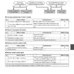
What are the common error codes for Yanmar V70S wheel loader?
Common error codes include 'Engine does not start up or starts up with difficulty' due to causes like 'Fuel tank empty' or 'Air in fuel system'. Another common fault is 'Engine gets too hot' which can be caused by 'Charge air pipe leaking' or a 'Coolant temperature transmitter defective'. p. 138
How quickly can I access this manual after buying?
Instant PDF download. You get the full 766-page searchable Service Manual immediately after payment. Open it on your laptop, tablet, or phone right in the shop.
Am I able to print pages from this manual?
No restrictions at all. Print individual pages, full chapters, or the entire manual. The PDF is completely unlocked.
Does this Service Manual have electrical diagrams?
Included. The Yanmar V70S Service Manual covers complete wiring harness diagrams, electrical circuits, and connector pinouts.


Reviews
There are no reviews yet.