


Part of the Yanmar Repair Manuals.
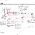
All 709 pages of this Yanmar ViO33-6, ViO38-6 Service Manual are factory-written for one purpose: returning your compact excavator to spec. Inside: hydraulic circuit schematics with complete fluid routing for both models, including the ViO38-6 ESS proportional solenoid valve, wiring diagrams covering the engine ECU and full machine electrical circuits, and a torque table section spanning machine fasteners, engine bolts, and hydraulic fittings. You also get error code lists for the electronic control system, step-by-step procedures for every major assembly from swing motor to fuel injection pump, and a troubleshooting quick-reference table to pinpoint faults fast. Torque the travel motor-to-track frame M12x30 bolts to 57.9-72.3 ft·lbf (78.5-98.0 N·m); idler seal cover to crawler adjust spring runs 32.6-43.4 ft·lbf (44.1-58.9 N·m). Your machine is down and the clock is running. Download now, jump to any section with bookmarks, and get the factory answer before you pull another bolt.
What's Inside This Yanmar ViO33-6, ViO38-6 Manual
| System | Pages | Key Topics |
|---|---|---|
| General Cautions for Maintenance Work | 12-23 | Correct Work, Safety Precautions, Preparations, Cautions for Disassembly and Reassembly, Cautions for Removal and Installation of Hydraulic Equipment |
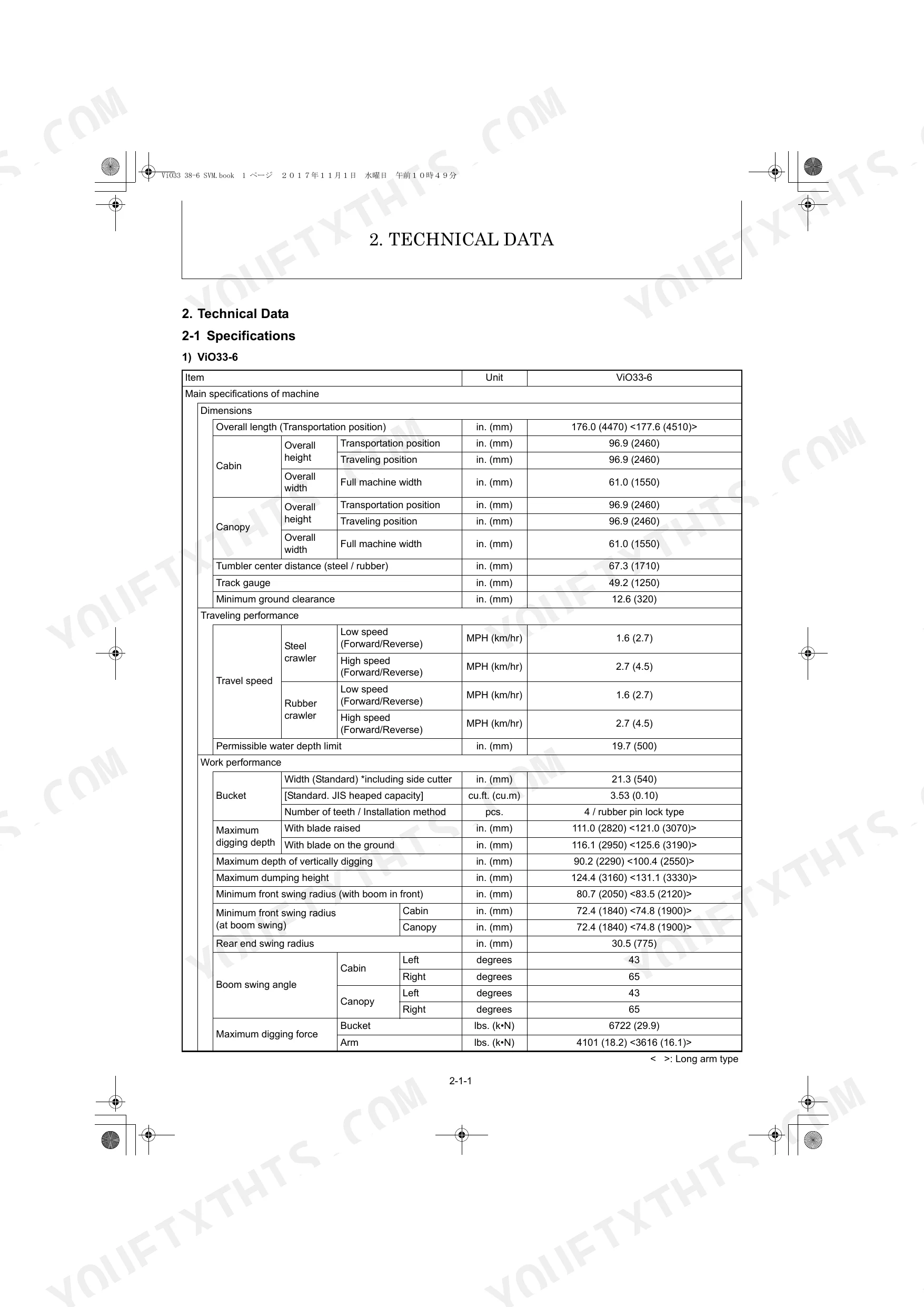
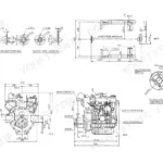
| Technical Data | 24-67 | 2-1 Specifications, 2-2 Outline Drawing and Working Area, 2-3 Weight List of Main Parts, 2-4 Lifting Capacity List, 2-5 Specifications for Attachment |
| Service Standards | 68-101 | Machine Performance, Engine, Undercarriage (Rubber Crawler Specifications, Steel Crawler Specifications, Common Specifications of Steel & Rubber Crawlers), Controls |
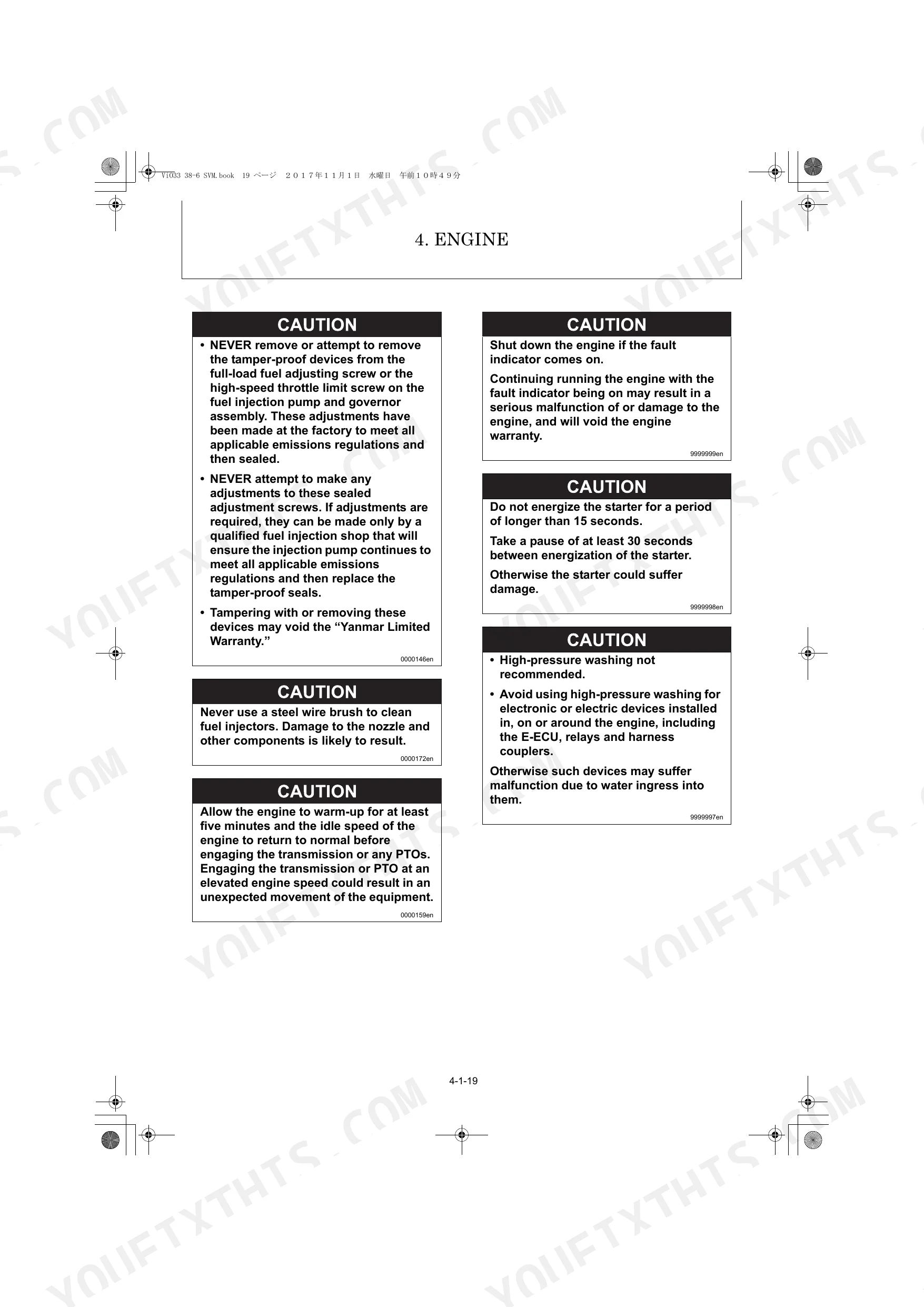
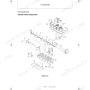
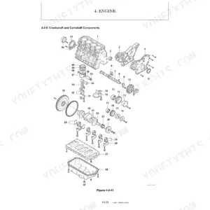
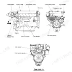
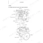
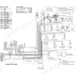
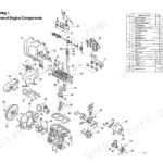
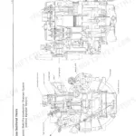
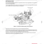
| Engine | 102-265 | 4-1 Engine, 4-2 Fuel System, 4-3 Cooling System, 4-4 Lubrication System, 4-5 Starter Motor, 4-6 Alternator, 4-7 Electronic Control System, 4-8 Electric Wiring |
| Electric System | 266-299 | 5-1 Electric Equipment of Machine, 5-2 Electronic Control System, 5-3 Engine ECU (Engine Controller), 5-4 Error Code List |
| Hydraulic System | 300-545 | 6-1 Outline, 6-2 Circuit Operation, 6-3 Hydraulic Pump, 6-4 Control Valve, 6-5 Pilot Valve, 6-6 Swing Motor, 6-7 Travel Motor, 6-8 Ess Proportional Solenoid Valve (ViO38-6 Only) |
| Adjustment and Repair | 546-694 | 7-1 Engine and Electric Equipment, 7-2 Undercarriage, 7-3 Controls, 7-4 Swing Bearing, 7-5 Hydraulic Equipment, 7-6 Work Implements, 7-7 Cabin, 7-8 Air Conditioner |
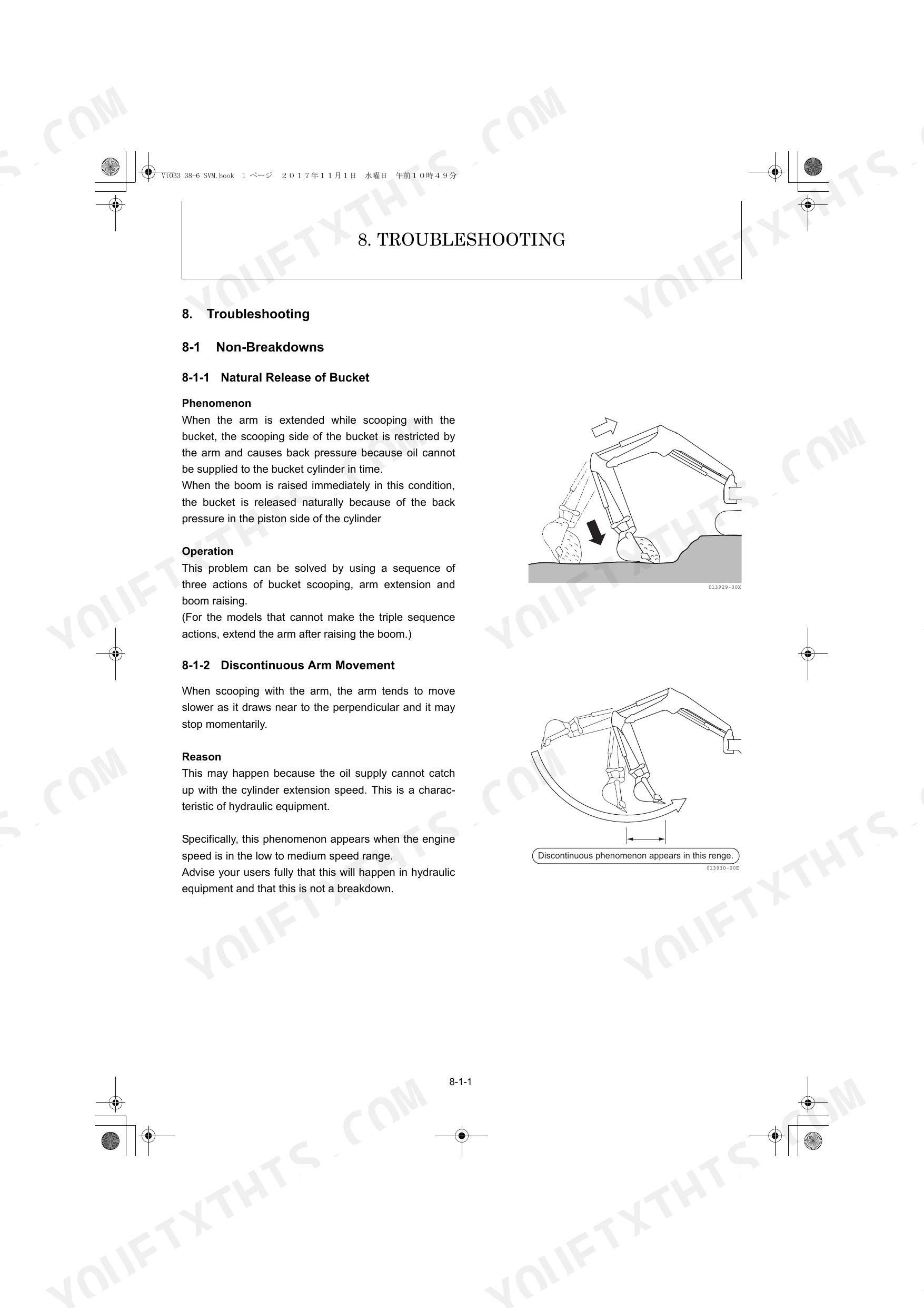
| Troubleshooting | 695-709 | 8-1 Non-Breakdowns, 8-2 Quick Reference Table for Troubleshooting |
Quick Reference Specifications
| Specification | Value | Page |
|---|---|---|
| Idler seal cover × Crawler adjust spring tightening torque | 32.6 to 43.4 ft·lbf (44.1 to 58.9 N·m) | p. 86 |
| Travel motor × Track frame tightening torque | 57.9 to 72.3 ft·lbf (78.5 to 98.0 N·m) | p. 87 |
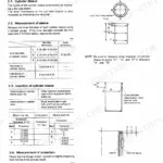
| Fuel filter filtration area | 310 (2000) sq.in. (sq.cm) | p. 29 |
| Suction filter type | CT-12W | p. 27 |
| Suction filter filtration area | 108 (697) sq.in. (sq.cm) | p. 27 |
| Air cleaner type | Cyclone type | p. 29 |
| Air cleaner filtration area | 12.8 (1.19) sq.ft. (sq.m) | p. 29 |
| Cooling water hose (Hose clip 41) tightening torque | 2.9 to 3.6 ft·lbf (3.9 to 4.9 N·m) | p. 85 |
| Cooling water hose (Hose clip 48) tightening torque | 3.6 to 4.4 ft·lbf (4.9 to 5.9 N·m) | p. 85 |
| Air cleaner intake hose (Hose clip 70) tightening torque | 1.8 to 2.5 ft·lbf (2.5 to 3.4 N·m) | p. 85 |
| Fan belt size | A38 | p. 29 |
| Oil/water separator filter mesh | 100 mesh | p. 29 |
Yanmar ViO33-6, ViO38-6 Common Problems This Manual Covers
Yanmar ViO33-6 / ViO38-6 hydraulic pump losing pressure, bucket or boom sluggish or unresponsive
Check hydraulic oil level first; tank holds 10.6 Gals (page 27) and running low starves the pump immediately. Inspect the suction filter (CT-12W, 150 mesh) and return filter (Y2502, 10 micron) for clogging before condemning the pump. Use the hydraulic system troubleshooting procedures starting on page 300 to verify circuit pressure against your model's relief specification.
Manual Section: Hydraulic System p. 27Engine cranks slowly or won't fire in cold weather, fuel system suspected
Drain the fuel-water separator bowl first; the 100-mesh element (page 29) collects water that freezes passages overnight. Verify fuel injection pressure falls between 2843 and 2988 PSI (page 30). Work through the engine fuel system procedures starting on page 102, checking the fuel filter for restriction (310 sq.in. filtration area) before condemning injectors.
Manual Section: Engine p. 30Coolant hose soft, cracked, or weeping at clamp after repeated heat cycles
Squeeze every hose cold; a soft or spongy wall means the inner liner is delaminating and will fail under pressure. Torque clip-41 clamps to 2.9 to 3.6 ft·lbf and clip-48 clamps to 3.6 to 4.4 ft·lbf (page 85). Verify coolant level before restart and check for air pockets in the system that indicate a past boil-over.
Manual Section: Engine p. 85Travel speed sluggish, one track pulls harder than the other, or machine veers
Check travel motor mounting bolt torque first; travel motor-to-track-frame bolts spec at 57.9 to 72.3 ft·lbf (page 87) and loose hardware causes binding that mimics hydraulic failure. Confirm hydraulic oil level (10.6 Gals capacity, page 27) and inspect both pilot valve connections. Consult the hydraulic system section starting on page 300 for travel circuit pressure tests.
Manual Section: Hydraulic System p. 87Swing rotation hesitates, drifts after stopping, or won't hold position on a slope
Inspect swing motor case drain lines for cloudy oil; milky fluid signals internal seal failure. Verify the pilot circuit is delivering adequate pressure before condemning the motor. Work through the hydraulic system section on page 300; compare measured swing speed against specifications on page 25 (ViO33-6: 10.5 rpm) or page 32 (ViO38-6: 9.5 rpm) to confirm the fault.
Manual Section: Hydraulic System p. 300Display flickers, work lights cut out, or machine throws an alert and shuts down
Pull active fault codes using the error code reference on page 290; codes narrow the fault to a specific circuit before you start probing connectors. Check battery voltage against the 12V / 55 Ah rating (page 30) and inspect all ground straps for corrosion. Trace display and switch wiring back to the fuse block; a loose pin causes intermittent shutdowns.
Manual Section: Electric System p. 290Frequently Asked Questions
What do the YANMAR ViO33-6 / ViO38-6 error codes mean?
The YANMAR ViO33-6 / ViO38-6 error codes are listed in the "5-4 Error Code List" section, starting on page 290. This list provides the error code, its classification (e.g., Caution, Warning), a description of the error (e.g., "Accelerator sensor malfunction: above normal operating range"), the detection condition, the causes, and corrective measures. For example, error code 00 000091.00 indicates an "Accelerator sensor malfunction: above normal operating range (SAEJ1843)". p. 290
What is the torque spec for the track tensioner, sprocket, or final drive bolts on a YANMAR ViO33-6 / ViO38-6?
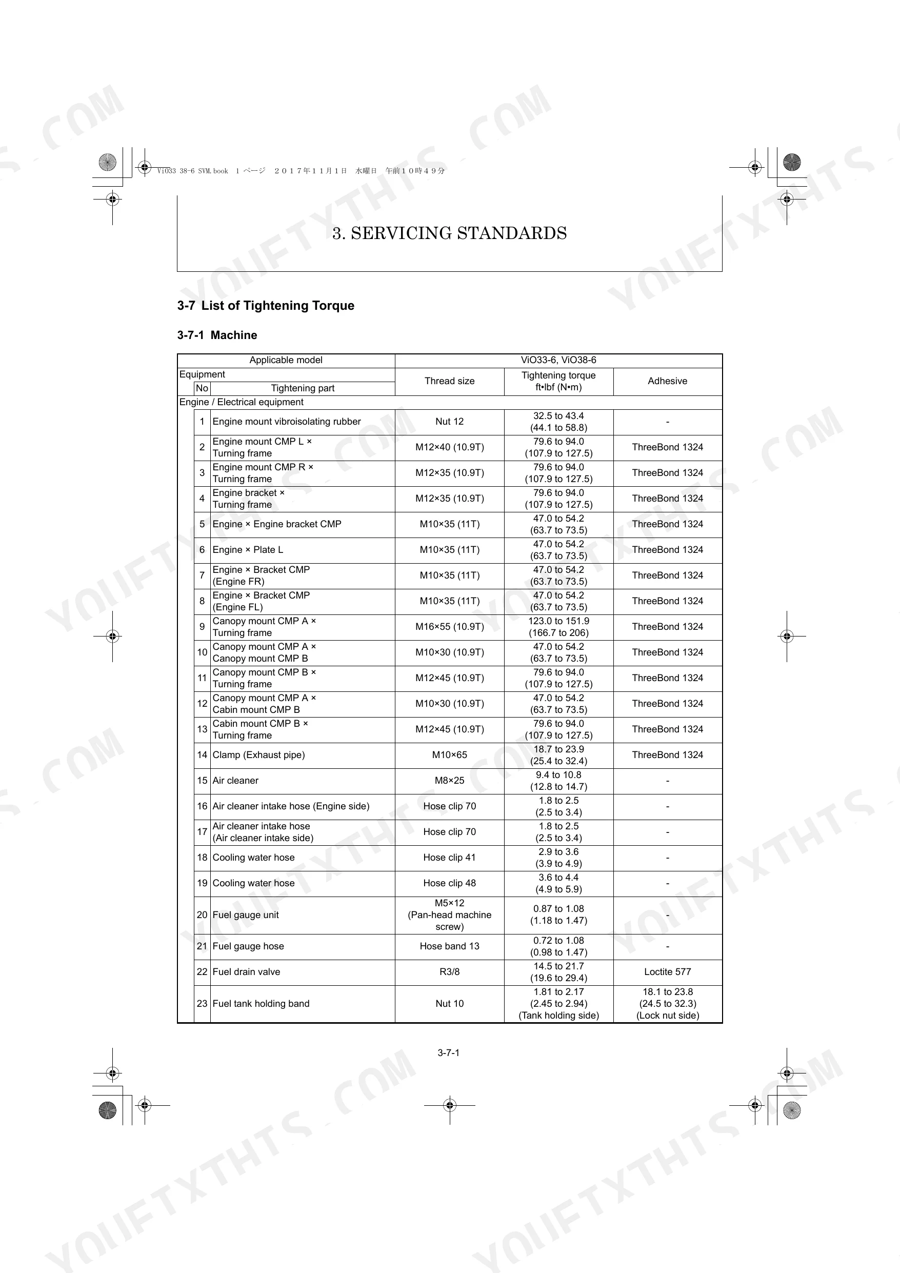
The tightening torque specifications for undercarriage components are as follows: For the sprocket (M12×35), the tightening torque is 57.9 to 72.3 ft·lbf (78.5 to 98.0 N·m). For the crawler adjust spring (M10×40), which is part of the tensioner, the torque is 32.6 to 43.4 ft·lbf (44.1 to 58.8 N·m). For the travel motor mounting bolts (M12), the torque is 57.9 to 72.3 ft·lbf (78.5 to 98.0 N·m). p. 86
How do I clear alarm codes on a YANMAR ViO33-6 / ViO38-6?
The manual does not provide a specific procedure to "clear" alarm codes in the sense of a reset button. Instead, for most alarm codes listed in the "5-4 Error Code List" (page 290), the corrective measure involves diagnosing and fixing the underlying cause, followed by cycling the ignition. For example, for an "Accelerator sensor malfunction" (Error code 00 000091.00), the manual advises to "Check the connectors, harnesses and engine control dial. Turn the starter switch to the “OFF” position and then the “ON” position. Then check that the error code is displayed again." This suggests that if the fault is resolved, the code may no longer be displayed after an ignition cycle. p. 290
How do I reset the hydraulic or fuel system after maintenance on a YANMAR ViO33-6 / ViO38-6?
After maintenance, the hydraulic system requires air release. For variable displacement piston pumps, run the engine at low idling for 5 to 10 minutes, check the oil level, and repeat. For hydraulic cylinders, run the engine at low idling, then slowly extend and retract cylinders 4 to 5 times up to 2 to 4 inches from each stroke end, followed by 3 to 4 full extensions and retractions. The fuel system needs to be primed; for electric fuel pumps, turn the key switch to ON for 10-15 seconds, and for mechanical pumps, operate the priming lever until the fuel filter cup is filled. p. 19
Is this Service Manual a digital download?
A 709-page Service Manual in searchable PDF format, available the moment you complete checkout. View on computer, tablet, or phone, with no shipping wait.
Can I print specific sections of this Service Manual?
Absolutely. No DRM or copy protection. Print the whole manual or just the pages you need. Any home or office printer works.
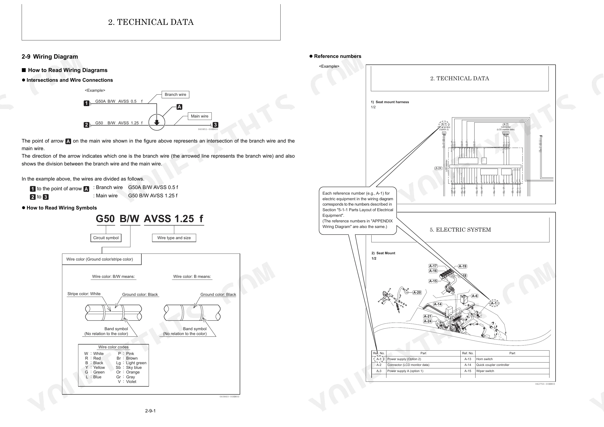
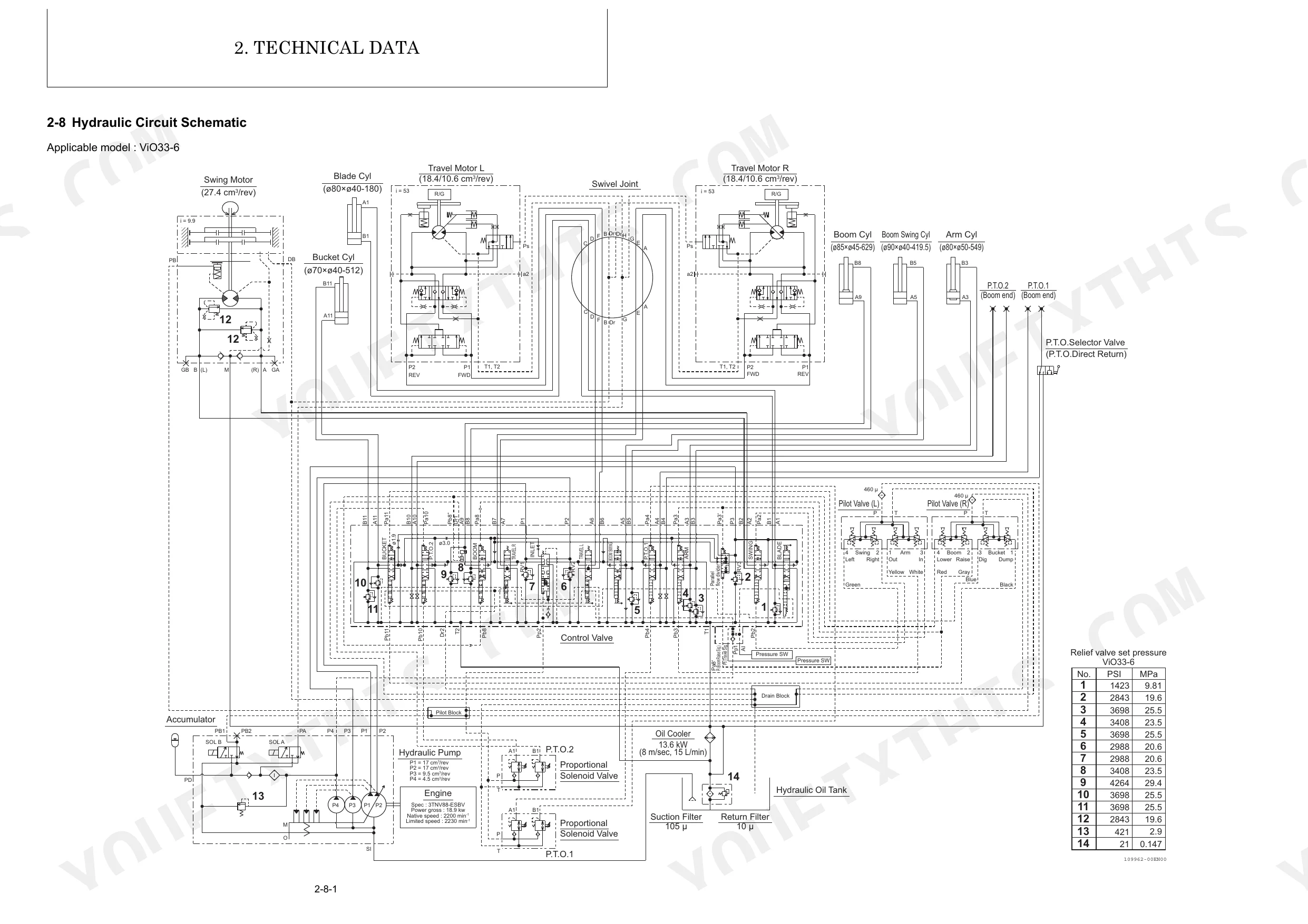
Are hydraulic system diagrams in this Yanmar ViO33-6, ViO38-6 Service Manual?
Included. Hydraulic system schematics cover all circuits, control valves, and component specifications for the Yanmar ViO33-6, ViO38-6.
Reviews
There are no reviews yet.