Part of the Yanmar Operator Manuals.
Need the exact factory operating and maintenance procedures for your marine auxiliary engine? This 33-page Yanmar 4CHL-N, 4CHL-TN, 6CHL-N, 6CHL-TN, 6CHL-HTN Operation Manual PDF (OEM #49961-300040) covers every fluid check, startup sequence, and periodic servicing task. Inside, you get complete electric wiring diagrams, detailed fuel and cooling system layouts, and a full table of periodic checking intervals. Open to the supercharger section for proper handling and air cooler maintenance, or use the step-by-step air bleeding procedures to get your fuel system primed. Keep the fuel injection valve pressure dialed at 220±10 kg/cm² and make sure the cylinder head bolts are tightened to exactly 16±1 kg-m. A dead auxiliary engine leaves you stranded on the water. Download this bookmarked file right to your tablet, find your spec in seconds, and keep your vessel running.
What's Inside This Manual
| System | Pages | Key Topics |
|---|---|---|
| Introduction | 2 | Operation, Maintenance and Inspection, Correct Engine Use, Engine Condition, Manual Accessibility, Manual Transfer, Product Improvements |
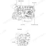
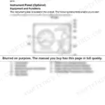
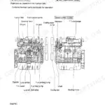
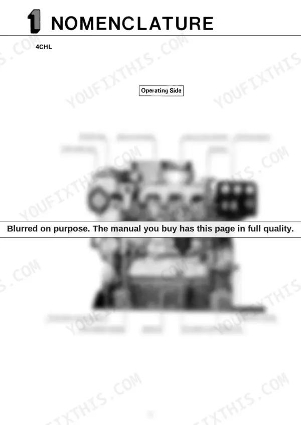
| Nomenclature | 5-6 | Pressure Cap, Suction Manifold, Lube Oil Filter Element, Instrument Panel, Exhaust Manifold, Alternator |
| Engine Specification | 7 | Model, Type, Combustion System, Cylinder Bore X Stroke, Rated Speed of Revolution, Firing Order |
| Instrument Panel & Adjustment | 8-10 | |
| Selection of Fuel Oil and Lubricating Oil | 11-12 | Selection and Handling of Fuel Oil, Selection of Lube Oil |
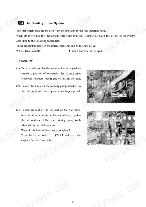
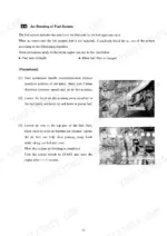
| Operation | 13-19 | Filling with Fuel Oil, Filling with Lube Oil, Filling with Cooling Water, Air Bleeding of Fuel System, Check Before Starting, Starting, Confirm Immediately After Starting |
| Handling of Supercharger | 20-21 | Check of Supercharger, Air Cooler (6CHL-HTN) |
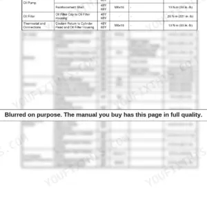
| Periodic Checking and Servicing | 22-27 | Table of Periodic Checking and Servicing |
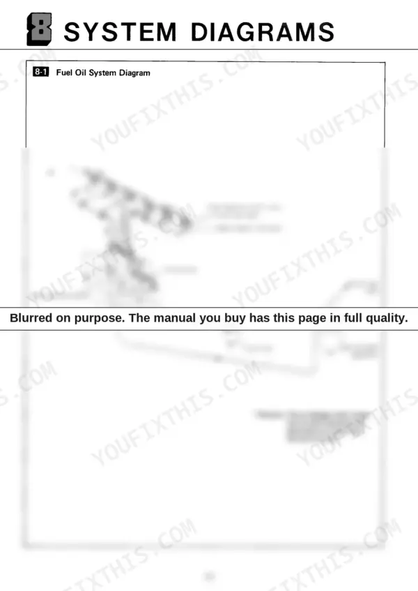
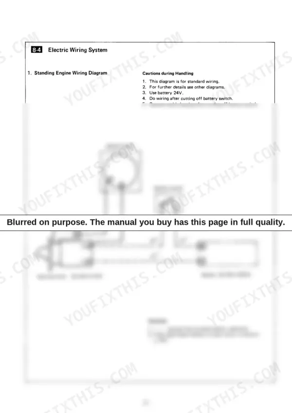
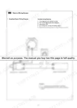
| System Diagrams | 28-33 | Fuel Oil System Diagram, Cooling Water System Diagram, Lube Oil System Diagram, Electric Wiring System |
Quick Reference Specifications
| Specification | Value | Page |
|---|---|---|
| Cylinder head bolt tightening torque | 16±1kg-m | p. 23 |
| Lube oil filter element replacement interval (first) | after 50 hours of operation (or one week) | p. 25 |
| Lube oil filter element replacement interval (subsequent) | every 500 hours of operation (or every 2 or 3 months) | p. 25 |
| Fuel valve tightening nut torque | 1±0.3 kg-m | p. 23 |
| Fuel injection valve pressure | 220±10kg/cm² | p. 23 |
| Air cooler draining interval | Every 50 hours (or weekly) | p. 21 |
| Exhaust manifold draining interval | Daily | p. 21 |
| Anticorrosive zinc plug change interval | Every 500 hours (or 2~3 months) | p. 21 |
| Normal lube oil pressure during operation | 3.5 – 4.5kg/cm² | p. 8 |
| Minimum lube oil pressure during warm-up | higher than 1.0kg/cm² | p. 17 |
| Cylinder Bore x Stroke | 105 x 125 mm | p. 7 |
| Starting System Voltage | DC24V | p. 7 |