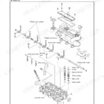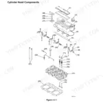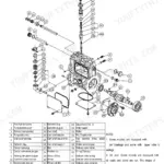



Part of the Yanmar Repair Manuals.
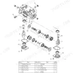
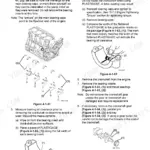
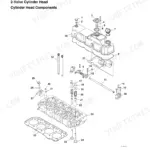
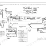
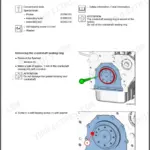
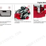
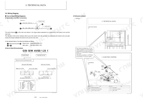
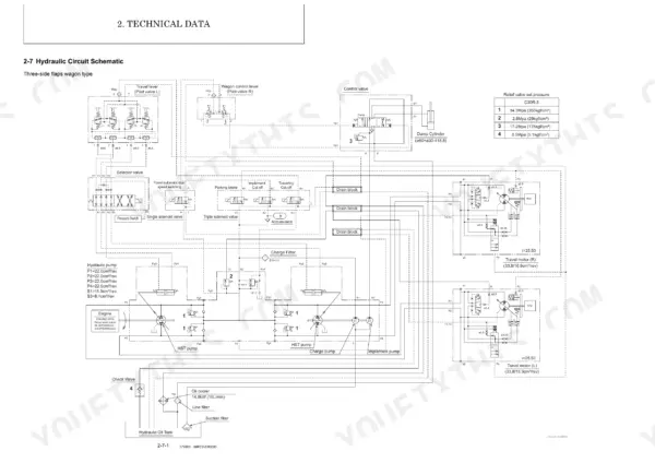
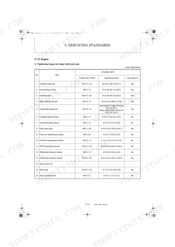
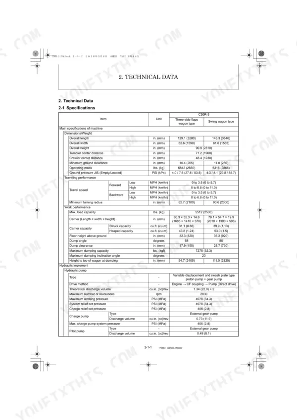
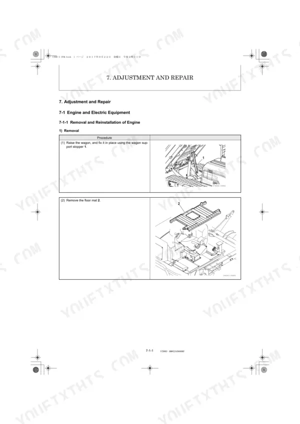
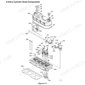
All 697 pages of this Yanmar C30R-3 Crawler Carrier Service Manual (OEM #0BKC2-EN0060) come straight from the factory, covering the diesel engine, full HST hydraulic system, travel motor, swing motor, control valve, and wagon assemblies. Inside: wiring diagrams, a complete hydraulic circuit schematic tracing fluid routing through every pump and pilot valve, and a full error code diagnostic section for engine ECU and machine faults. You also get a service standards chapter loaded with torque tables for hydraulic fittings and engine fasteners, plus step-by-step adjustment and repair procedures across the engine, undercarriage, controls, hydraulic equipment, and wagon. Set the parking brake release pressure to 406 PSI (2.8 MPa) and fill the hydraulic system to 38L (three-side flaps wagon) or 40L (swing wagon type) before startup. Your carrier is down. Bookmarked for instant navigation, search any spec by keyword and get back to work.
Complete the set for your C30R-3
- Parts Catalog: Yanmar C30R-3, 4TNV88C-KFW Parts Catalog
What's Inside This Manual
| System | Pages | Key Topics |
|---|---|---|
| Spine | 2 | |
| General Cautions for Maintenance Work | 13-26 | Correct Work, Safety Precautions, Preparations, Cautions for Disassembly and Reassembly, Cautions for Removal and Installation of Hydraulic Equipment |
| Technical Data | 27-54 | 2-1 Specifications, 2-2 Outline Drawing and Working Area, 2-3 Weight List of Main Parts, 2-4 Power Transmission, 2-5 List of Periodic Inspection and Servicing, 2-6 Fuel |
| Service Standards | 55-84 | Machine Performance (Three-Side Flaps Wagon Type, Swing Wagon Type), Engine (Nominal and Allowable Values), Undercarriage, Controls, Hydraulic Cylinder, Work Implement |
| Engine | 85-259 | 4-1 Safety, 4-2 Engine, 4-3 Fuel System, 4-4 Cooling System, 4-5 Lubrication System, 4-6 Starter Motor, 4-7 Alternator, 4-8 Electronic Control System |
| Electric System | 260-315 | 5-1 Electric Equipment of Machine, 5-2 Circuit Description of Engine Start and Stop, 5-3 vCircuit Description of Engine Start and Stop, 5-4 Engine ECU (Engine Controller) |
| Hydraulic System | 316-522 | 6-1 Outline, 6-2 Component Parts, 6-3 Circuit Operation, 6-4 Hydraulic Pump (HST), 6-5 Travel Motor, 6-6 Swing Motor, 6-7 Control Valve, 6-8 Pilot Valve |
| Adjustment and Repair | 523-672 | 7-1 Engine and Electric Equipment, 7-2 Undercarriage, 7-3 Controls, 7-4 Hydraulic Equipment, 7-5 Wagon |
| Troubleshooting | 673-697 | 8-1 Troubleshooting |
Quick Reference Specifications
| Specification | Value | Page |
|---|---|---|
| Hydraulic oil capacity (Three-side flaps wagon type) | 10 Gals (38 L) | p. 39 |
| Hydraulic oil capacity (Swing wagon type) | 10.6 Gals (40 L) | p. 39 |
| Air cleaner filtration area | 12.8 sq.ft. (1.19 sq.m) | p. 30 |
| Air cleaner element replacement interval | Every 500 hrs | p. 37 |
| Parking brake release pressure | 406 PSI (2.8 MPa) | p. 27 |
| Hydraulic pump maximum working pressure | 4978 PSI (34.3 MPa) | p. 27 |
| Travel motor displacement (Low/High) | 2.06 in3/rev (33.8 cm3/rev) / 1.03 in3/rev (16.9 cm3/rev) | p. 28 |
| Track roller shaft A wear limit | Ø2.439 in. (Ø61.69 mm) | p. 66 |
| Sprocket A wear limit | 0.91 in. (23 mm) | p. 66 |
| Machine not moving straight after travel/brake service or hydraulic work | Perform air bleeding (follow steps 1 and 3 to 12 on page 21) and warm-up before travel if at low hydraulic oil temperatures. | p. 22 |
| Hydraulic oil overflow during air release | Hydraulic oil begins to overflow through the air breathers (3, 4, 5, and 6) | p. 21 |
| Rubber track A wear limit | 0.32 in. (8 mm) | p. 66 |