


Part of the John Deere Repair Manuals.
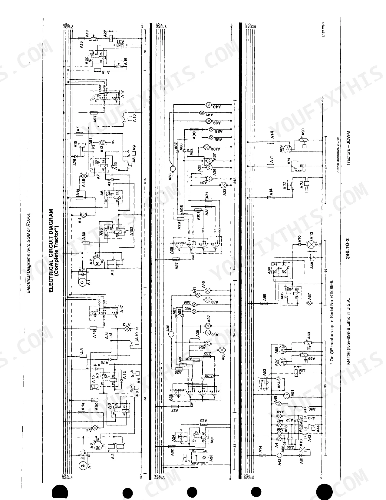
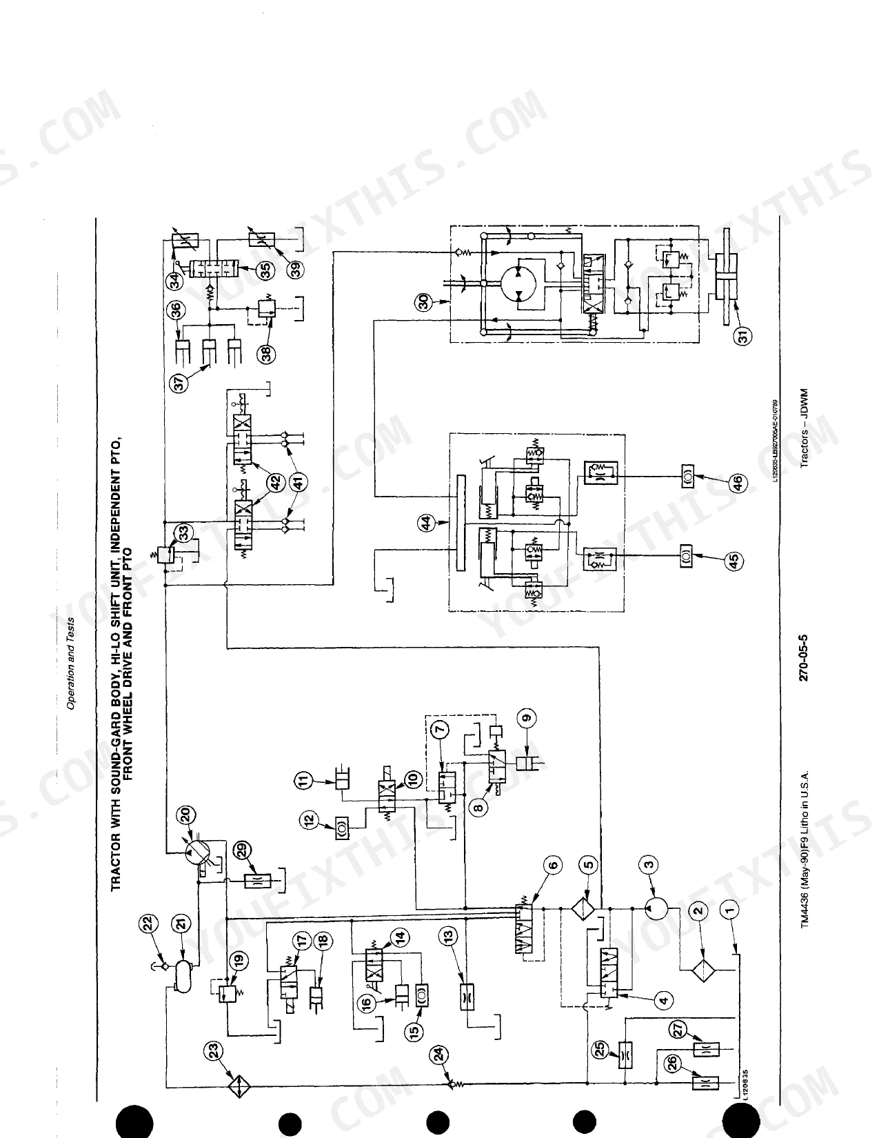
All 525 pages of this John Deere 2155 technical manual (OEM TM4436) focus on a single goal: restoring the 2155, 2355N, 2355, 2555, 2755, 2855N, 2955, and 3155 tractors to factory condition. You get full wiring diagrams tracing every circuit from the charging system to the cab HVAC, hydraulic schematics routing the complete rockshaft and selective control valve circuits, a thorough troubleshooting section that works through electrical and mechanical faults system by system, and step-by-step procedures for the power train, Hi-Lo shift unit, FWD disk clutch, and hydrostatic steering. Pressure-test your cooling system to 50-70 kPa (7-10 psi); the intake vacuum limit for a clean air element is 6 kPa. Every hour that tractor sits costs money. Download it now, open any section in seconds using bookmarked navigation, and get the factory answer on your first look.
What's Inside This John Deere 2155–3155 Series Manual
| System | Pages | Key Topics |
|---|---|---|
| Safety | - | Observe Safety Rules, Handle Fluids Safely, Prevent Battery Explosions, Park Machine Safely, Use Tools Properly, Live with Safety |
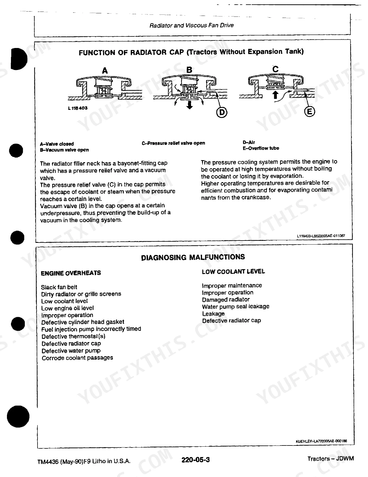
| Engine | - | Radiator Specifications, Radiator Cap Function, Diagnosing Malfunctions, Cooling System Leaks, Viscous Fan Drive Function, Dynamometer Test |
| Fuel and Air Intake System | - | Fuel Tank Description, Water Trap, Ether Starting Fluid Aid, Fuel Preheater, Speed Control Linkage, Air Cleaner Function |
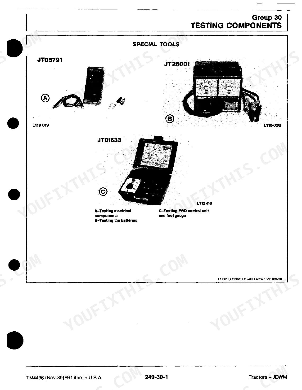
| Electrical Equipment | - | How to Read Circuit Diagram, System Malfunctions, Electrical Circuit Malfunctions, Testing Components, Starting Motor Function, Alternator Function |
| Power Train | - | Clutch Operating Linkages, Hi-Lo Shift Unit, Reverser Operation, Synchronized Transmission, Differential Lock, Front PTO, FWD Disk Clutch |
| Steering System and Brakes | - | Hydrostatic Steering Operation, Steering Valve Assembly, Metering Unit Function, Power Steering Circuit, Hydraulic Brakes Operation, Handbrake Description |
| Hydraulic System | - | Hydraulic System Description, Graphic Symbols for Hydraulics, Valves, Filters, Oil Cooler, Hydraulic Pumps, Rockshaft Operation, Selective Control Valves |
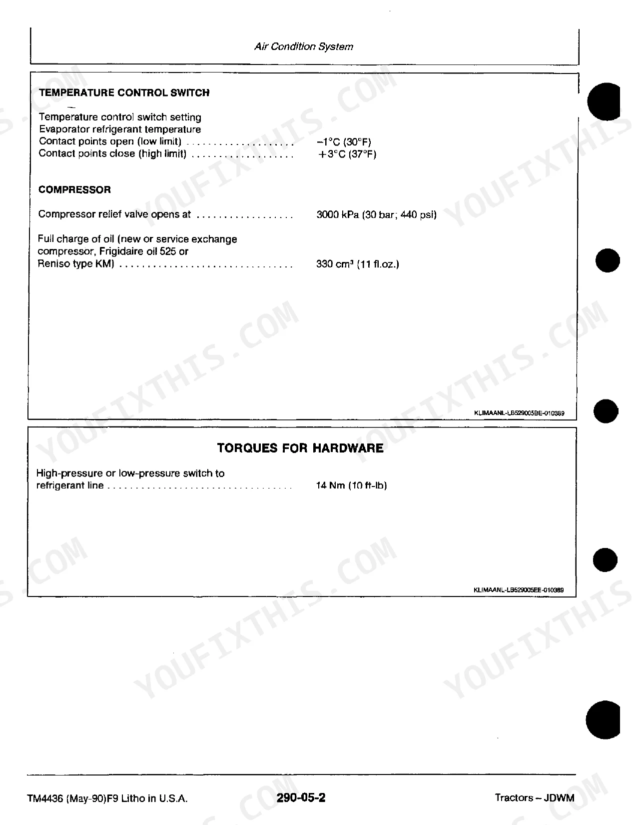
| Operator's Station | - | Air Conditioning System Cycle, Refrigerant Characteristics, Temperature Control Switch, Compressor Relief Valve, Receiver-Drier, Cab Ventilation and Heating |
Quick Reference Specifications
| Specification | Value | Page |
|---|---|---|
| All Models | ||
| Air intake system vacuum (clean element) | approx. 3.5 kPa (35 mbar; 14 in. water head) (should not exceed 6 kPa (60 mbar; 25 in. water head)) | p. 36 |
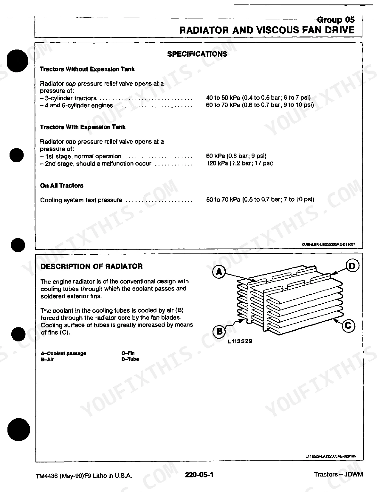
| Cooling system test pressure | 50 to 70 kPa (0.5 to 0.7 bar; 7 to 10 psi) | p. 15 |
| Radiator cap pressure relief valve (Expansion Tank, 1st stage) | 60 kPa | p. 15 |
| Alternator voltage (increasing engine speed) | 13.7 to 14.5 volts | p. 221 |
| Alternator output current (85 A alternator, 1500 rpm) | 30 amps | p. 221 |
| Hi-Lo Shift Unit operating pressure (1500 rpm) | 1050 kPa | p. 241 |
| FWD disk clutch operating pressure | 1050 kPa | p. 317 |
| Hydrostatic Steering shock valves adjustment pressure | 21000 kPa | p. 333 |
| Hydraulic System, flow control valve opening pressure | 12300 kPa | p. 417 |
| 2155, 2355N, 2355 | ||
| Radiator cap pressure relief valve (3-cylinder tractors) | 40 to 50 kPa (0.4 to 0.5 bar; 6 to 7 psi) | p. 15 |
| 2555, 2755, 2855N, 2955, 3155 | ||
| Radiator cap pressure relief valve (4 and 6-cylinder engines) | 60 to 70 kPa (0.6 to 0.7 bar; 9 to 10 psi) | p. 15 |
| 3-cylinder tractors | ||
| Radiator cap pressure relief valve | 40 to 50 kPa | p. 15 |
John Deere 2155–3155 Series Common Problems This Manual Covers
John Deere 2355 engine cranks but won't fire, white smoke on cold start after high-hour service gap
Replace the primary fuel filter if service has exceeded 600 hours. Bleed air at the injection pump vent screw before cranking. Verify the fuel shutoff valve is fully open and drain the water trap. Follow the engine no-start sequence. If injection pump output is suspect, bench-test delivery pressure.
Manual Section: Fuel and Air Intake SystemHydraulic steering becomes stiff or unresponsive, requires excessive wheel effort to turn at low speed
Inspect hydraulic oil level and check for contamination before pressure testing. Connect a gauge to the steering circuit and verify shock valve pressure reaches 21000 kPa (page 333). If pressure is low, remove and inspect the metering unit seals. Replace steering cylinder rod seals if external leakage is visible at the cylinder body.
Manual Section: Steering System and Brakes p. 333Engine temperature gauge climbs into red zone under load with no visible coolant loss or external leaks
Pressure-test the cooling system to 50-70 kPa (page 15) and monitor for pressure drop over five minutes. Inspect the radiator core for debris packing; in dusty conditions, cores clog well before 6000 hours. Test thermostat opening temperature in boiling water and check water pump impeller for corrosion or pitting. Follow for viscous fan drive diagnosis.
Manual Section: Engine p. 15Air cleaner restriction indicator light stays on after replacing the filter element, no engine power loss noticed
Attach a vacuum gauge to the air intake test point. A clean element should read approximately 3.5 kPa (page 36); replace immediately if vacuum exceeds 6 kPa (60 mbar; 25 in. water head). If vacuum is within spec and the indicator persists, test restriction switch continuity and wiring back to the instrument cluster per service procedures.
Manual Section: Fuel and Air Intake System p. 36Rockshaft fails to raise implement, settles under load, or rises erratically in depth control mode
Check hydraulic oil level and inspect the filter for metal debris. Verify the flow control valve opens at 12300 kPa (page 417); low pressure points to pump wear or a sticking valve spool. Inspect the rockshaft control valve for contamination and confirm the spool moves freely through full travel. Test response at operating temperature before disassembling the pump.
Manual Section: Hydraulic System p. 417Battery drains overnight or fails to hold charge, alternator warning light on during field operation
Measure alternator output with a multimeter: at increasing engine speed, voltage must read 13.7 to 14.5 volts (page 221). At 1500 rpm, an 85-amp alternator should produce at least 30 amps. Clean and retorque the B+ terminal and chassis ground strap connections. Load-test the battery separately before condemning the alternator or voltage regulator.
Manual Section: Electrical Equipment p. 221Frequently Asked Questions
What fluids and capacities does this machine require?
The air conditioning system requires Refrigerant R-12 with a capacity of 1.8 kg (4 lb). For new or service exchange compressors, a full charge of oil (Frigidaire oil 525 or Reniso type KM) is 330 cm3 (11 fl.oz.). The refrigerant is a colorless, odorless, non-toxic, non-corrosive gas that mixes with refrigerant oil. p. 481
How to troubleshoot engine won't start?
If the engine won't start, common issues include a sluggish or inoperative starting motor. Check for a low battery output, loose or corroded terminals, defective cables or wires, or a faulty main switch. If the solenoid switch "chatters," it indicates low battery output or loose/corroded connections. p. 53
What are the hydraulic system specifications?
The hydraulic system operates with a system pressure of 15900 to 16200 kPa (159 to 162 bar; 2300 to 2350 psi). The surge relief valve in the clutch housing opens at 690 to 760 kPa (6.9 to 7.9 bar; 100 to 110 psi), and the flow control valve opens at 12300 kPa (123 bar; 1800 psi). p. 391
What torque specifications are listed?
For the MFWD clutch, the minimum torque before slippage is 880 Nm (650 ft-lb) for APL 315 and 325 axles, 1200 Nm (885 ft-lb) for APL 325N and 735 axles, and 1300 Nm (955 ft-lb) for APL-350 axles. When testing the steering valve geroter, apply 7 Nm (60 in-lb) torque to the steering shaft. The high-pressure or low-pressure switch to the refrigerant line should be torqued to 14 Nm (10 ft-lb). p. 329
How quickly can I access this manual after buying?
You get a 525-page searchable PDF that downloads instantly after checkout. Open it on your laptop, tablet, or phone, and bring it right to the shop floor.
Are there any print restrictions on this manual?
No restrictions at all. Print individual pages, full chapters, or the entire manual. The PDF is completely unlocked.
Can I find hydraulic circuit diagrams in this John Deere 2155 & variants manual?
A hydraulic system diagram for the John Deere 2155 & variants is included.


Reviews
There are no reviews yet.