


![John Deere 110 Repair Manual [Lawn & Garden Tractor]](https://youfixthis.com/wp-content/uploads/2012/02/Manual_Download-300x300.jpg)
Part of the John Deere Repair Manuals.
This John Deere Technical Manual (TM1426) covers the 240, 245, 260, 265, 285, and 320 lawn and garden tractors built from serial number 130000. It is the same factory service documentation John Deere wrote for dealer technicians, spanning 562 pages across twelve sections.The manual covers all three engines used across this family: the FC420V on the 240 and 245, the FC540V on the 260 and 265, and the FD590V on the 285 and 320. You get full specifications, component locations, theory of operation, troubleshooting charts, tests and adjustments, and step by step repair procedures.Beyond the engines, it details the electrical system with schematics and test points, both the gear and hydrostatic power trains, steering, hydraulics, and fuel injection. With torque values, clearances, and diagnostic steps included, an owner or independent mechanic can service and rebuild these tractors with confidence.
What's Inside This John Deere 240–320 Manual
| System | Pages | Key Topics |
|---|---|---|
| Safety | 4-11 | - |
| General Information | 12-49 | Specifications, O-Ring Information, Metric Fastener Torque Values, Inch Fastener Torque Values, Fuel Information, Lubrication Information, Coolant Information |
| FC420V Engine | 50-109 | Specifications, Component Location, Theory of Operation, Troubleshooting, Tests & Adjustments, Repair |
| FC540V Engine | 110-169 | Specifications, Special or Essential Tools, Other Materials, Service Parts Kits, Component Location, Troubleshooting, Tests & Adjustments, Repair |
| FD590V Engine | 170-241 | Specifications, Special or Essential Tools, Dealer Fabricated Tools, Other Materials, Service Parts Kits, Component Location, Theory of Operation, Troubleshooting |
| Fuel Injection System | 242-245 | Remove, Inspect and Install Fuel Pump, Remove and Install Fuel Tank, Inspect Fuel Tank |
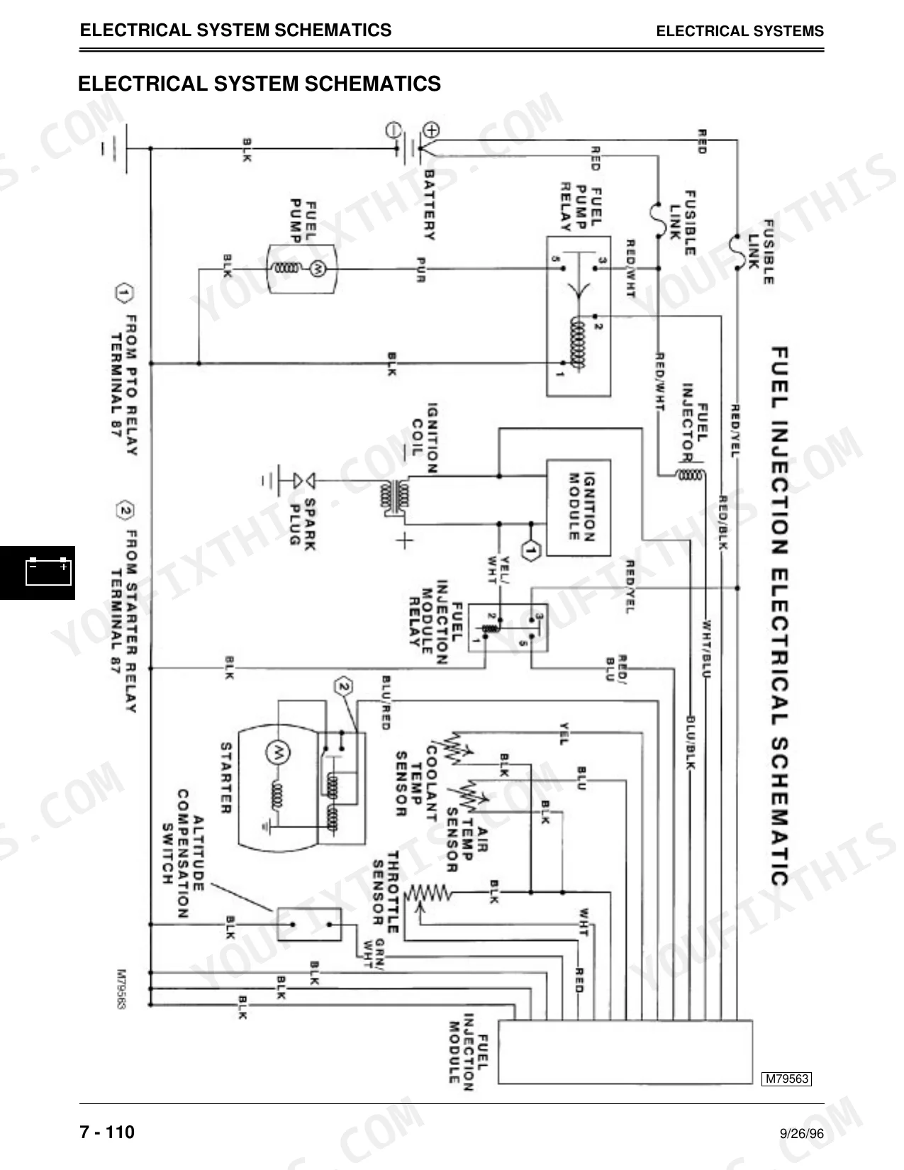
| Electrical System | 246-370 | Theory Information, Component Location, Theory of Operation, Diagnosis, Test Points, Tests, Schematics |
| Gear Power Train | 371-418 | Component Location, Theory of Operation, Diagnosis, Adjustments, Specifications, Other Material, Repair |
| Hydrostatic Power Train | 419-488 | Component Location, Theory of Operation, Diagnosis, Adjustments, Specifications, Repair |
| Steering | 489-496 | Component Location, Theory of Operation, Diagnosis, Adjusments, Repair |
| Hydraulics | 497-520 | Component Location, Theory of Operation, Diagnosis, Tests, & Adjustments, Other Material, Repair |
| Miscellaneous | 521-552 | Component Location, Theory of Operation, Diagnosis, Tests, & Adjustments, Repair |
Quick Reference Specifications
| Specification | Value | Page |
|---|---|---|
| All Models | ||
| Mower deck belt tension | Not specified as a numerical value for resetting; manual refers to condition of tensioning components and replacement of belt if worn or damaged. | p. 529 |
| Hydraulic lift linkage adjustment | Adjust linkage | p. 517 |
| Key Switch Continuity (Off position) | M—G (A and B) continuity | p. 348 |
| Key Switch Continuity (Run position) | B—A (C and D) continuity | p. 348 |
| Seat Switch Continuity | Continuity only when plunger is depressed | p. 351 |
| 240, 245 | ||
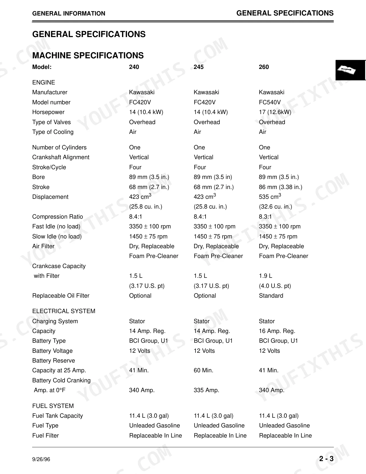
| Cylinder Head Cap Screw Torque (Initial) | 32 N·m (283 lb-in.) | p. 53 |
| Cylinder Head Cap Screw Torque (Final) | 52 N·m (38 lb-ft) | p. 53 |
| Starter Amp Draw (Max.) | 60 amps at 500 rpm | p. 18 |
| 240, 245, 260 | ||
| Battery Type | BCI Group, U1 | p. 14 |
| 265, 285, 320 | ||
| Battery Type | BCI Group, 22F | p. 15 |
| 260, 265 | ||
| Starter Amp Draw (Max.) | 85 amps at 500 rpm | p. 18 |
| 245, 265, 285, 320 | ||
| Transmission Neutral Switch Continuity (Hydrostatic) | Continuity only when plunger is depressed (brake pedal depressed) | p. 349 |
John Deere 240–320 Common Problems This Manual Covers
Hard starting after sitting
These tractors often crank slowly or fail to fire after sitting or with a weak battery, pointing to the starter circuit, battery, or grounds. The Electrical System section walks through component locations, test points, and starting circuit diagnosis.
Manual Section: Section 7 - Electrical System p. 246Cranks but will not start
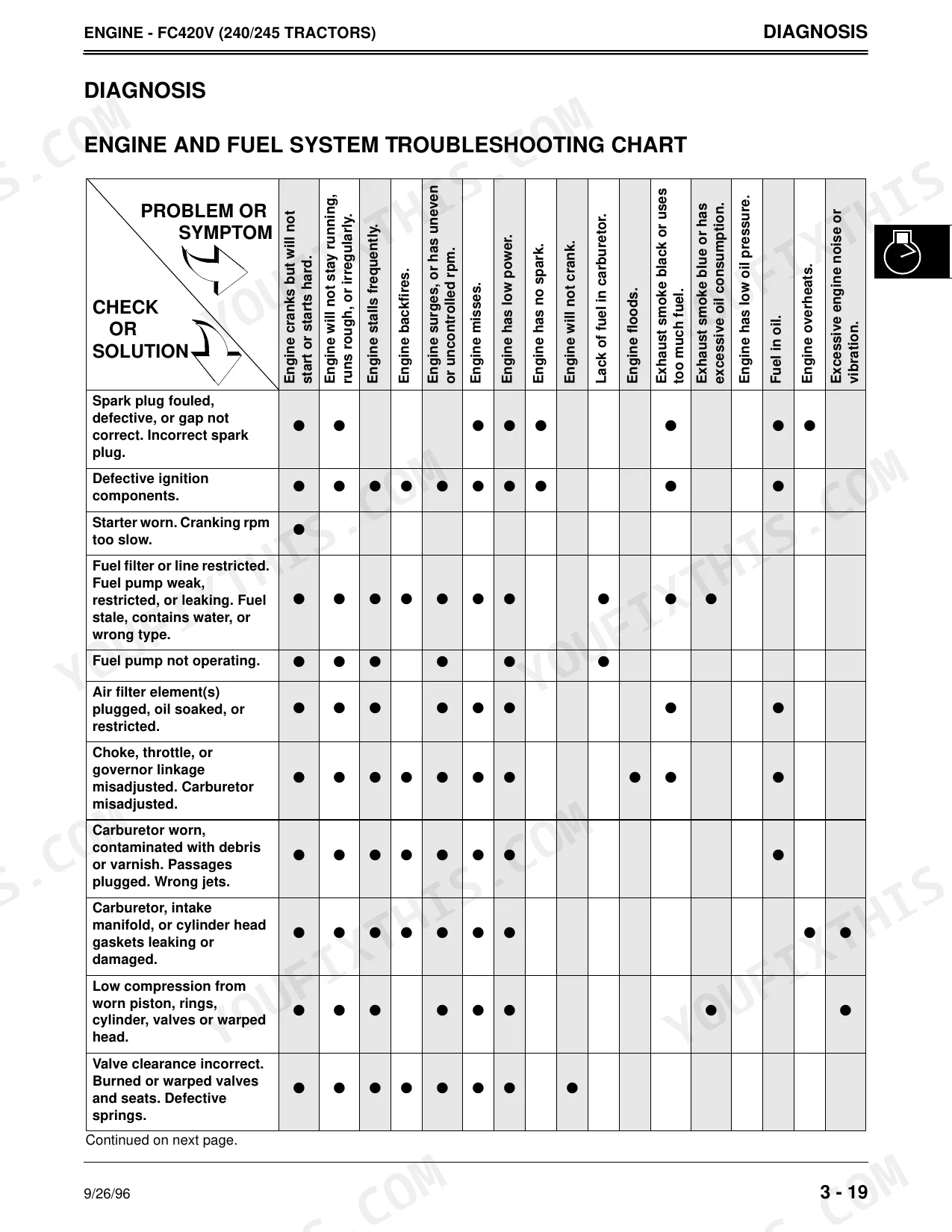
A common failure is an engine that cranks but will not start, or fires briefly and dies, usually from fuel delivery, carburetor, or ignition faults. The FC420V Engine section provides the troubleshooting chart, tests, and adjustments to trace it.
Manual Section: Section 3 - FC420V Engine p. 50Weak or no hydrostatic drive
Owners of the 245, 265, 285, and 320 report the tractor moving weakly or not at all, often from hydrostatic wear, low fluid, or linkage problems. The Hydrostatic Power Train section covers diagnosis, adjustments, and repair.
Manual Section: Section 9 - Hydrostatic Power Train p. 419PTO or mower deck will not engage
The PTO or mower deck can fail to engage due to a worn drive belt, faulty switch, or linkage wear. The Miscellaneous section covers component location, theory of operation, diagnosis, and repair for these driven attachments.
Manual Section: Section 12 - Miscellaneous p. 521Hydraulic lift will not raise
A lift that will not raise or hold on the 285 and other models often traces to worn linkage or a hydraulic fault. The Hydraulics section provides component location, diagnosis, tests and adjustments, including the lift linkage adjustment on page 517.
Manual Section: Section 11 - Hydraulics p. 497Overheating or power loss under load
The FD590V engines on the 285 and 320 can lose power or overheat from restricted cooling, low oil, or tuning issues. The FD590V Engine section covers theory of operation, troubleshooting, tests, and adjustments to correct it.
Manual Section: Section 5 - FD590V Engine p. 170Frequently Asked Questions
Which tractors and engines does this manual cover?
It covers the John Deere 240, 245, 260, 265, 285, and 320 lawn and garden tractors from serial number 130000, including the FC420V, FC540V, and FD590V engines, plus the electrical, power train, steering, and hydraulic systems.
Where are the engine torque specifications?
Torque values are in each engine section. The FC420V Engine section lists specifications such as cylinder head, spark plug, and connecting rod cap screw torques, so you can tighten fasteners to the correct values during a rebuild. p. 50
Does it help diagnose a no move or weak drive problem?
Yes. The Hydrostatic Power Train section provides component location, theory of operation, diagnosis, adjustments, and repair procedures for the 245, 265, 285, and 320, so you can trace loss of motion to its source. p. 419
Are wiring schematics and starting diagnosis included?
Yes. The Electrical System section includes theory of operation, component location, test points, tests, and full schematics, covering the starting circuit and safety interlocks that cause no crank or no start faults. p. 246
How will I receive this John Deere 240 & variants Technical Manual?
The complete 562-page searchable Technical Manual downloads right away. Read it on a laptop at your desk or a phone out in the field.
Can I print this John Deere 240 & variants manual?
No restrictions at all. Print individual pages, full chapters, or the entire manual. The PDF is completely unlocked.
Are there hydraulic schematics in this John Deere 240 & variants manual?
Yes, this John Deere 240 & variants Technical Manual includes hydraulic system diagrams, circuit schematics, and component specifications.