


Part of the John Deere Repair Manuals.
This is the John Deere 3200 and 3400 Telescopic Handler technical manual, publication TM4626, covering 724 pages of factory repair and diagnostic procedures. It applies to both the 3200 and 3400 models, which run the 4.5 L (100 hp) PowerTech diesel engine.The manual is split into two halves: repair sections that show how to rebuild components, and operation and tests sections that help you diagnose faults. You get coverage of the engine and cooling system, fuel and air intake, electrical system, power train and torque converter, brakes and steering, hydraulics, the boom, and the operator's cab and air conditioning.Every section lists the special tools, torque values, and wear tolerances needed for the job, so an owner or independent mechanic can trace a warning light, correct brake pressure, or overhaul the hydraulic pump without guessing. It is delivered as a downloadable PDF you can search, print, and keep on any device.
What's Inside This John Deere 3200, 3400 Manual
| System | Pages | Key Topics |
|---|---|---|
| Safety | 5-16 | Group 05, Safety Information (Recognize Safety Information, Understand Signal Words, Live with Safety, Wear Protective Clothing, Service Machines Safely, Work in Ventilated Area, Illuminate Work Area Safely, Use Proper Tools, Construct Dealer-Made Tools Safely, Practice Safe Maintenance, Protect Against Noise, Use Proper Lifting Equipment, Support Machine Properly, Work in Clean Area, Handle Fluids Safely, Avoid Fires, Park Machine Safely, Prevent Battery Explosions, Prevent Acid Burns, Avoid High-Pressure Fluids, Avoid Heating Near Pressurized Fluid Lines, Remove Paint Before Welding or Heating, Service Tires Safely, Replace Safety Signs, Prepare for Emergencies, Dispose of Waste Properly) |
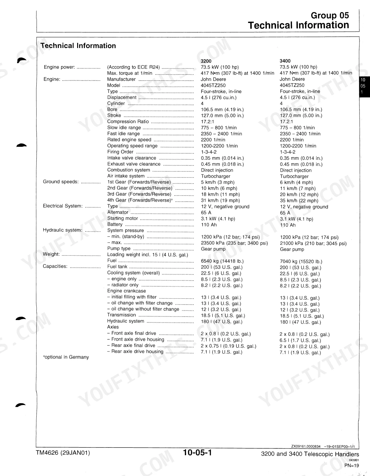
| General Information | 17-40 | Group 05, Technical Information (Dimensions, 3200 Telescopic Handler, Dimensions, 3400 Telescopic Handler) |
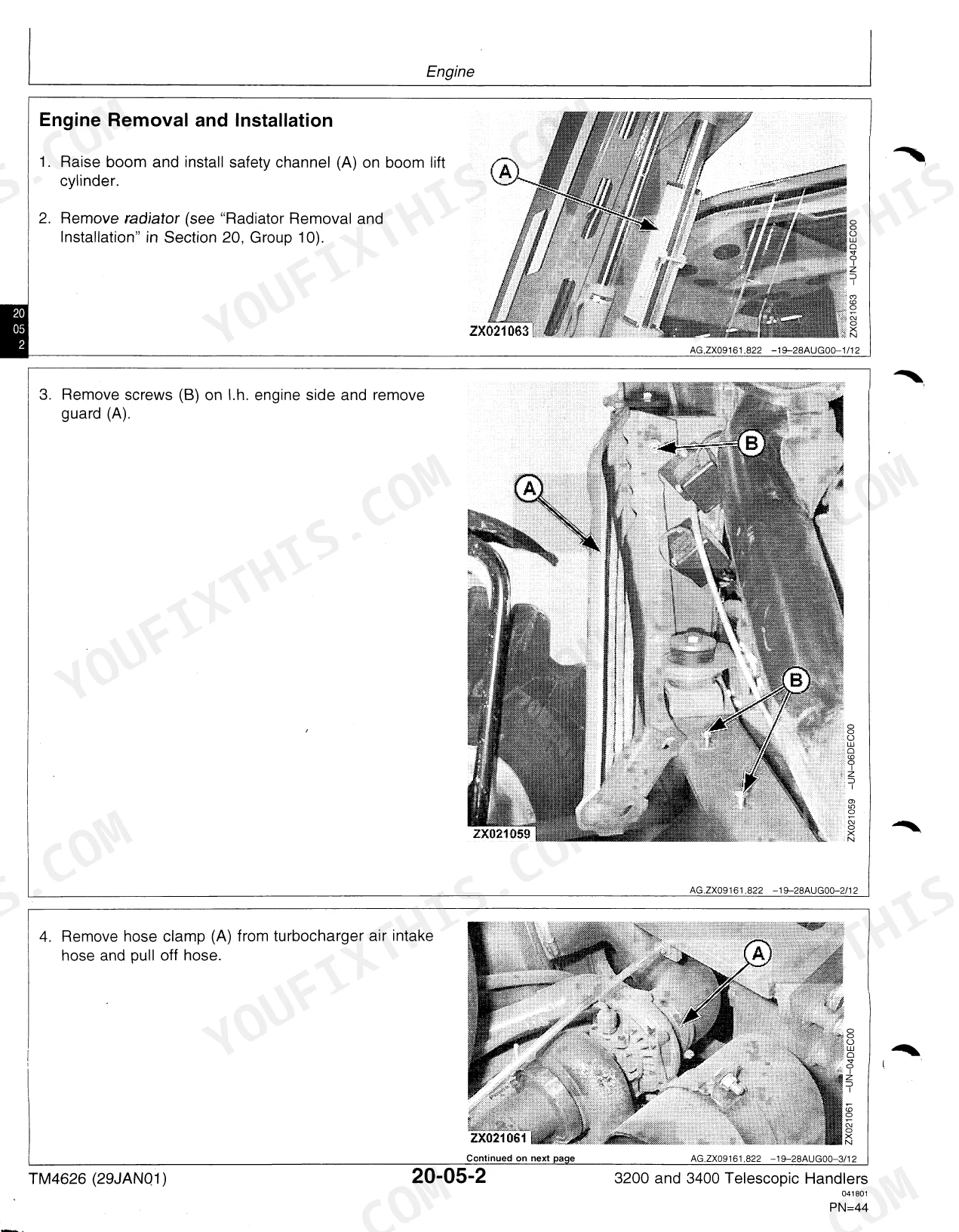
| Engine, Repair | 41-56 | Engine, Cooling System |
| Fuel/Air Intake Systems, Repair | 57-64 | Fuel System, Air Intake System |
| Electrical System, Repair | 65-108 | Group 05, Electrical Connectors (Special or Essential Tools, Electrical Repair Tool Kit, Electrical Connector Handling, Disconnecting Electrical Circuit, Remove Connector Body From Blade Terminals, Insulated/Non-Insulated Connectors, Replace Small Mate-N-Lok™ Pin Connector, Replace Cpc, Large Mate-N-Lok and Metrimate™ Pin Type Connectors, Replace Cpc Blade Type Connectors, Replace Sure-Seal™ Connectors, Replace Deutsch™ Connectors, Install Deutsch™ Contact, Replace Weather Pack™ Connector, Install Weather Pack™ Contact) |
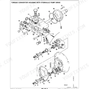
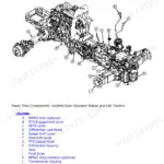
| Power Train, Repair | 109-206 | Group 05, Torque Converter Unit (Special or Essential Tools, Special Tools, Self-Manufactured, Special Tool, Repair Specifications, Removal of Torque Converter Unit, Disassemble Torque Converter Unit, Drive Shaft Disassembly and Assembly, Replace Output Shaft Bearings, Inspect Transmission Pump, Assemble Torque Converter Unit, Installation of Torque Converter Unit) |
| Brake and Steering Systems, Repair | 207-250 | Group 05, Service Brakes (Special or Essential Tools, Repair Specifications, Hydraulic Line Torques, Brake System Accumulator, Removing and Installing Accumulator, Accumulator Charge Valve Removal and Installation, Accumulator Pressure Switch Removal and Installation, Brake Valve Removal and Installation, Brake Valve Repairs, Correct Preset Brake Pressure, Correct Maximum Brake Pressure, Bleed Service Brakes) |
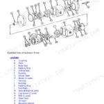
| Hydraulic System, Repair | 251-290 | Group 05, Hydraulic Pump (Repair Instructions, Hydraulic Pump Removal, Hydraulic Pump Exploded View, Hydraulic Pump Installation) |
| Miscellaneous, Repair | 291-318 | Group 05, Boom (Repair Specifications, Other Material, Boom Design, Boom Removal and Installation, Inner Boom Removal and Installation, Replacing Front Wear Plates, Replacing Rear Wear Plates, Carrier Pivot Plate Removal and Installation, Carrier Change-Over Valve, Lowering Boom in Case of Hydraulic Failure) |
| Operator’s Cab, Air Conditioning System, Repair | 319-384 | Group 05, Operator’s Cab (Special or Essential Tools, Other Material, Repair Specifications, Operator’s Cab Removal and Installation, Replace Door Lock, Operator’s Cab Door Removal and Installation, Replace Rear Window, Replace Glued-In Windows, Cab Rear Panelling Removal and Installation) |
| Engine, Tests | 385-388 | Engine Tests |
| Fuel/Air Intake Systems, Tests | 389-392 | Air Intake System |
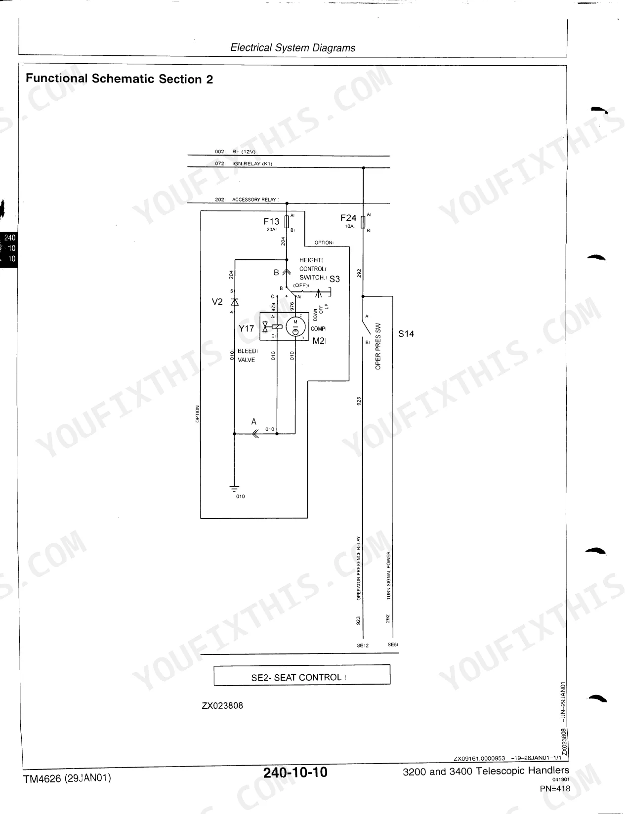
| Electrical System, Tests | 393-607 | Test Equipment, Electrical System Diagrams, Starting Motor Power Supply, Seat Adjustment, Windshield Wiper/Washer System, Heating/Air Conditioning System, Radio |
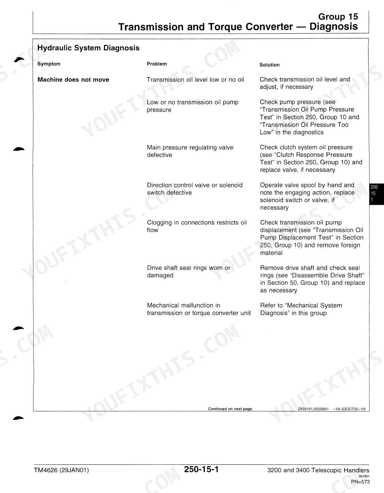
| Power Train, Tests | 608-637 | Transmission and Torque Converter, Theory of Operation, Tests, Diagnosis |
| Brake and Steering Systems, Tests | 638-665 | Brake System, Brake System Tests, Steering System, Theory of Operation, Steering Unit Test |
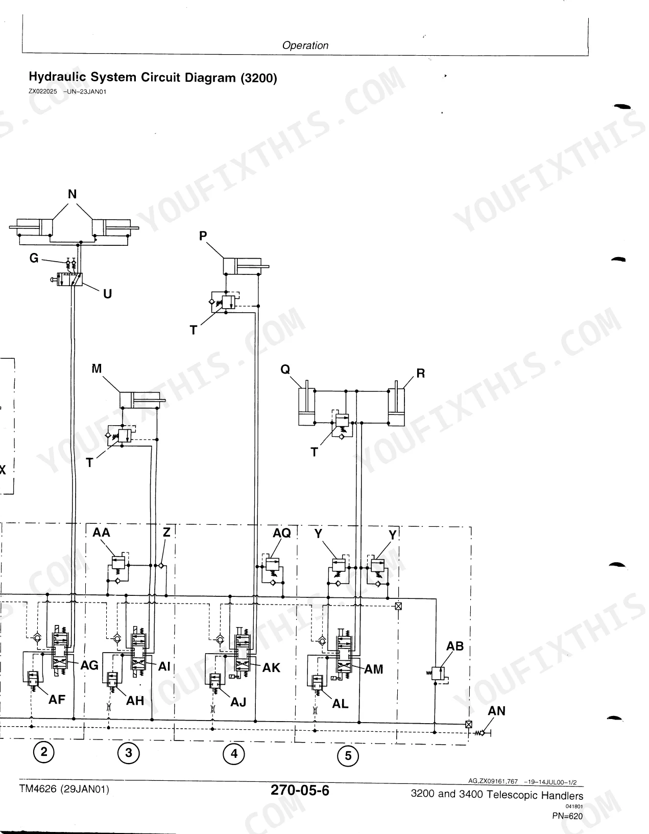
| Hydraulic System, Tests | 666-699 | Operation, Valves, Hydraulic System Tests |
| Heater, Air Conditioning, Tests | 700-724 | Operation, Tests |
Quick Reference Specifications
| Specification | Value | Page |
|---|---|---|
| All Models | ||
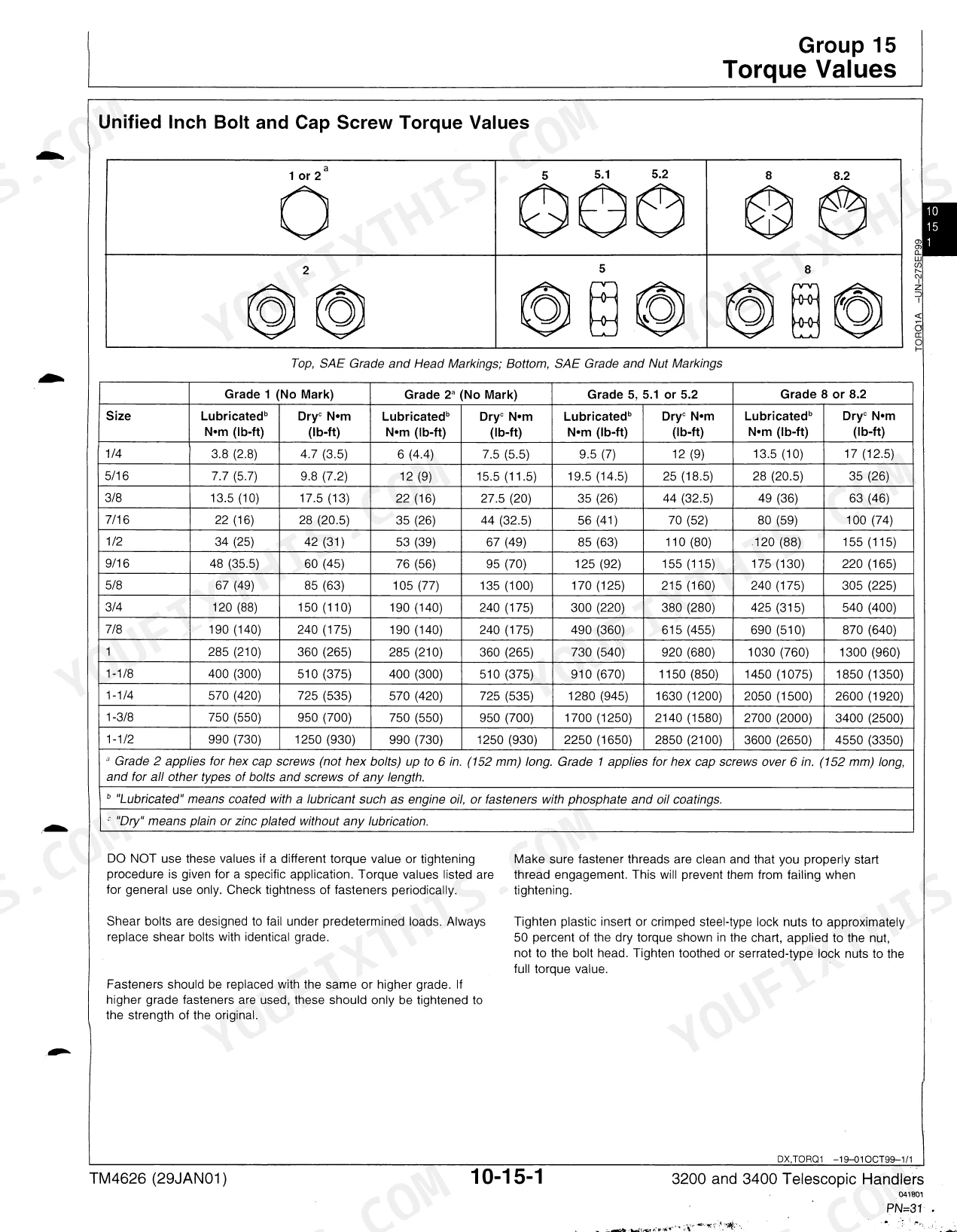
| Wheel nuts torque | 550 N*m (400 Ib-ft) | p. 198 |
| Hydraulic System BSP Fitting Torques (1/4") | 33 N*m (24 Ib-ft) | p. 35 |
| Filter element retaining screw torque | 30 N*m (22 Ib-ft) | p. 205 |
| Engine Power (ECE R24) | 73.5 kW (100 hp) | p. 19 |
| Engine Displacement | 4.5 L (276 cu.in.) | p. 19 |
| Fuel Tank Capacity | 200 L (53 U.S. gal.) | p. 19 |
| Engine Crankcase Oil Change with Filter | 13 L (3.4 U.S. gal.) | p. 19 |
| Transmission Oil Volume | 18.5 L (5.1 U.S. gal.) | p. 19 |
| Hydraulic System Oil Volume | 180 L (47 U.S. gal.) | p. 19 |
| Brake System Preset Pressure | 70 - 150 kPa (0.7 - 1.5 bar; 10 - 22 psi) | p. 209 |
| 3200 handler model | ||
| Hydraulic System Max Pressure | 23500 kPa (235 bar; 3407 psi) | p. 668 |
| 3400 handler model | ||
| Hydraulic System Max Pressure | 21000 kPa (210 bar; 3045 psi) | p. 668 |
John Deere 3200, 3400 Common Problems This Manual Covers
Hard starting in cold weather
Owners report poor starting on these telehandlers, especially in winter. The engine tests section walks through the diagnostic checks to isolate whether the cause is fuel, compression, or the starting circuit.
Manual Section: Engine - Tests p. 385Joystick control faults
Joystick problems are a common complaint and affect boom and hydraulic control. The electrical tests section covers the boom control system diagrams and signals so you can trace the fault before replacing the joystick.
Manual Section: Electrical System - Tests p. 393Low brake system oil pressure warning
A red warning light for low hydraulic pressure in the power braking system means the machine should not be operated. The brake repair section covers the accumulator, charge valve, pressure switch, and how to correct preset and maximum brake pressure.
Manual Section: Brake and Steering Systems - Repair p. 207Boom pins and bushings wear
Pins and bushings around the boom and carrier wear over time and cause slop under load. The boom repair section covers front and rear wear plate replacement and carrier pivot plate service.
Manual Section: Miscellaneous - Repair p. 291Hydraulic and transmission filter clogged
A filter indicator light glowing with the engine running points to a clogged hydraulic/transmission oil filter. The hydraulic repair section covers the pump and related service so you can restore flow after replacing the element.
Manual Section: Hydraulic System - Repair p. 251Alternator warning light stays on
An alternator indicator that glows with the engine running usually means an alternator defect or a bad alternator cable. The electrical repair section covers the alternator, battery, and connector repairs needed to fix it.
Manual Section: Electrical System - Repair p. 65Air cleaner restriction indicator
An air cleaner indicator light signals a restricted or dirty air intake element. The fuel and air intake repair section covers the air intake system so you can service the element and clear the warning.
Manual Section: Fuel/Air Intake Systems - Repair p. 57Frequently Asked Questions
Which machines does this manual cover?
It covers the John Deere 3200 and 3400 Telescopic Handlers, publication TM4626, both fitted with the 4.5 L PowerTech diesel engine. Repair and test procedures apply to both models, with model-specific values called out where they differ.
What is the engine power and displacement?
The engine produces 73.5 kW (100 hp) under ECE R24 and displaces 4.5 L (276 cu.in.). These and other technical specifications are listed in the General Information section. p. 17
What is the hydraulic system maximum pressure?
Maximum hydraulic pressure is 23500 kPa (235 bar; 3407 psi) on the 3200 and 21000 kPa (210 bar; 3045 psi) on the 3400. The Hydraulic System tests section covers valve operation and system pressure checks. p. 666
Does it include wiring diagrams and electrical diagnostics?
Yes. The Electrical System tests section provides system diagrams and test procedures for the starting motor supply, seat adjustment, wiper/washer, heating and air conditioning, and radio circuits. p. 393
What do I get after purchasing this John Deere 3200, 3400 manual?
Checkout delivers a 724-page searchable PDF for instant download. Open it on a laptop, tablet, or phone and bring it right to the shop floor.
Are there any print restrictions on this John Deere 3200, 3400 manual?
Absolutely. No DRM or copy protection. Print the whole manual or just the pages you need. Any home or office printer works.
Are electrical wiring diagrams included in this John Deere 3200, 3400 manual?
Yes, this John Deere 3200, 3400 Technical Manual includes complete electrical wiring diagrams, wire routing, and connector pinouts.


Reviews
There are no reviews yet.