


![John Deere 5220 5320 5420 5520 Diagnostic Technical Manual [Tractors]](https://youfixthis.com/wp-content/uploads/2012/02/Manual_Download-300x300.jpg)
Part of the John Deere Repair Manuals.
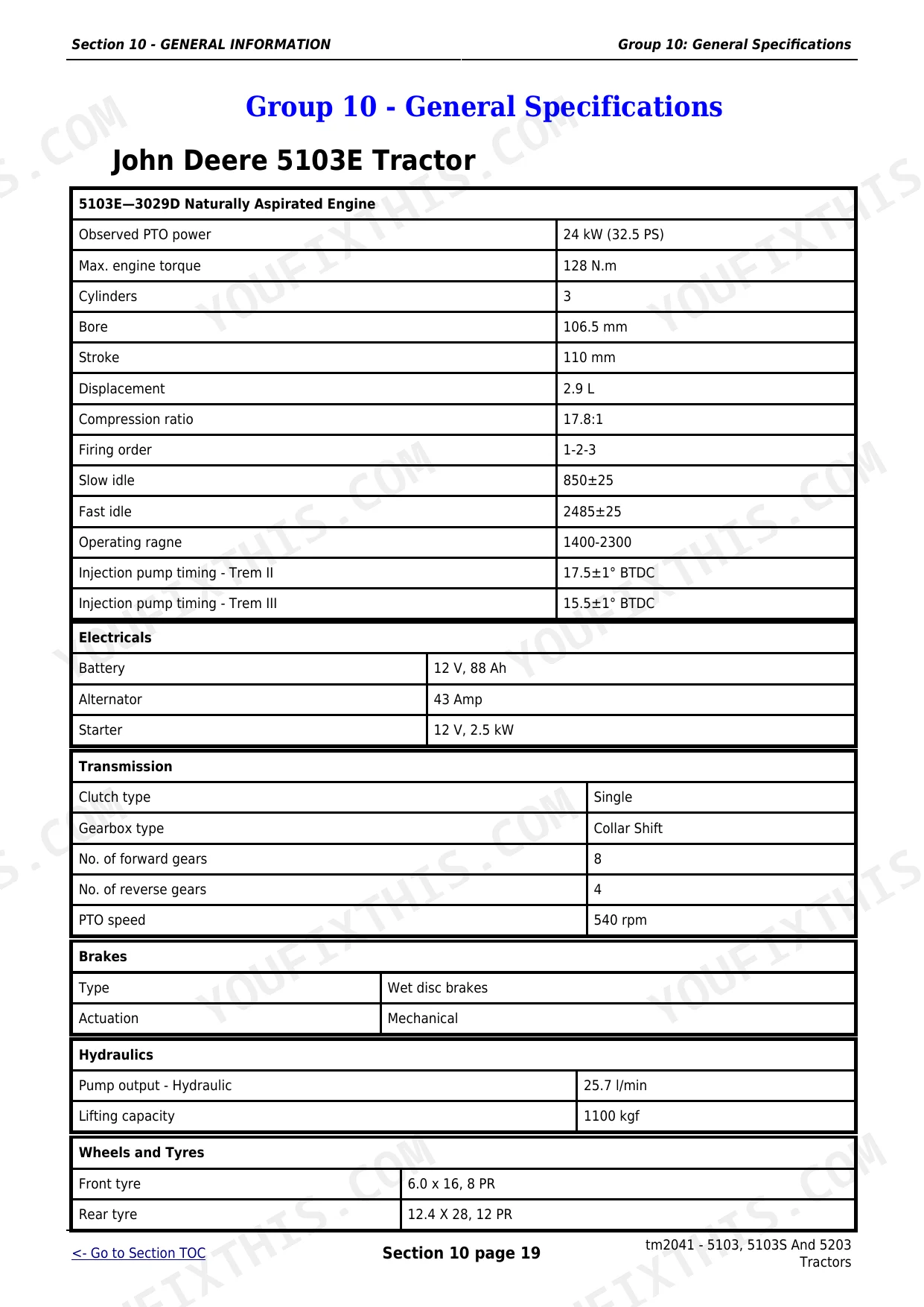
This is the John Deere technical manual tm2041 for the 5038D, 5103, 5103E, 5103S, 5104, 5203, and 5204 tractors, all built around the 3029D naturally aspirated diesel engine. It runs 1370 pages and is split into repair sections and operation, tests, and adjustments sections, the way John Deere organizes its dealer-level service documentation.With it you can work through engine, fuel and air, electrical, power train, steering and brake, and hydraulic repair, then use the operational checkout and diagnostic sections to isolate a fault before you open anything up. Torque values, clearances, and service procedures are called out for each component group, including separate electrical coverage for the 5103E.The file is a downloadable PDF you can search, print, and keep on the machine or the shop computer.
What's Inside This John Deere 5038–5204 Manual
| System | Pages | Key Topics |
|---|---|---|
| General Information | 8-76 | Safety (Recognize Safety Information, Understand Signal Words, Follow Safety Instructions, Handle Fluids Safely, Avoid Fires, Prevent Battery Explosions) |
| Engine Repair | 77-298 | Engine (Service Equipment and Tools, Specifications, John Deere Engine Repair, Use CTM8) |
| Fuel and Air Repair | 299-318 | Fuel System (Special or Essential Tools, Self-Manufactured Tool Template for Front Plate Replacement, Specifications, Torques for Hardware, Injection Pump, Nozzle and Governor Repair) |
| Electrical Repair | 319-358 | Battery, Starter and Alternator (Starter Repair, Use CTM77, Remove and Install Battery, Remove and Install Starter, Replace Alternator/Regulator) |
| Power Train Repair | 359-586 | Clutch Housing (Specifications, Separate Engine From Transmission Housing, Install Engine to Transmission Housing, Inspect and Repair Clutch Pedal and Linkage) |
| Steering and Brake Repair | 587-657 | Steering Repair (Other Material, Specifications, Service Parts Kits, Remove and Install Steering Column and Valve, Disassemble and Inspect Steering Valve, Assemble Steering Valve) |
| Hydraulic Repair | 658-759 | Hydraulic Pump and Filter (Essential Tools, Specifications, Service Parts Kits, Remove, Inspect, And Install Hydraulic Oil Pick-Up Screen) |
| Miscellaneous Repair | 760-795 | Front Axle (Specifications, Remove and Install Front Axle, Inspect and Replace Pivot Pin and Bushings, Remove and Install Spindle Assembly, Inspect and Replace Spindle Shaft Bushings) |
| Operator Station Repair | 796-810 | Seat and Support (Specifications, Remove and Install Deluxe Seat and Support, Remove and Install Standard Seat and Support) |
| Operational Checkout Procedures | 811-838 | Operational Checkout Procedures (Operational Checkout Procedure Information, Engine Oil Level and Condition Check, Coolant Level and Condition Check, Transmission and Hydraulic Oil Check, Fan and Belt Check, Fuel System Check) |
| Engine Operation, Tests and Adjustments | 839-894 | Component Location (Component Location Information, Engine External Components, Left-Hand Side, Right-Hand Side) |
| Fuel/Air Operation, Tests and Adjustments | 895-917 | Component Location (Component Location Information, Fuel System Components, Air Intake System Components) |
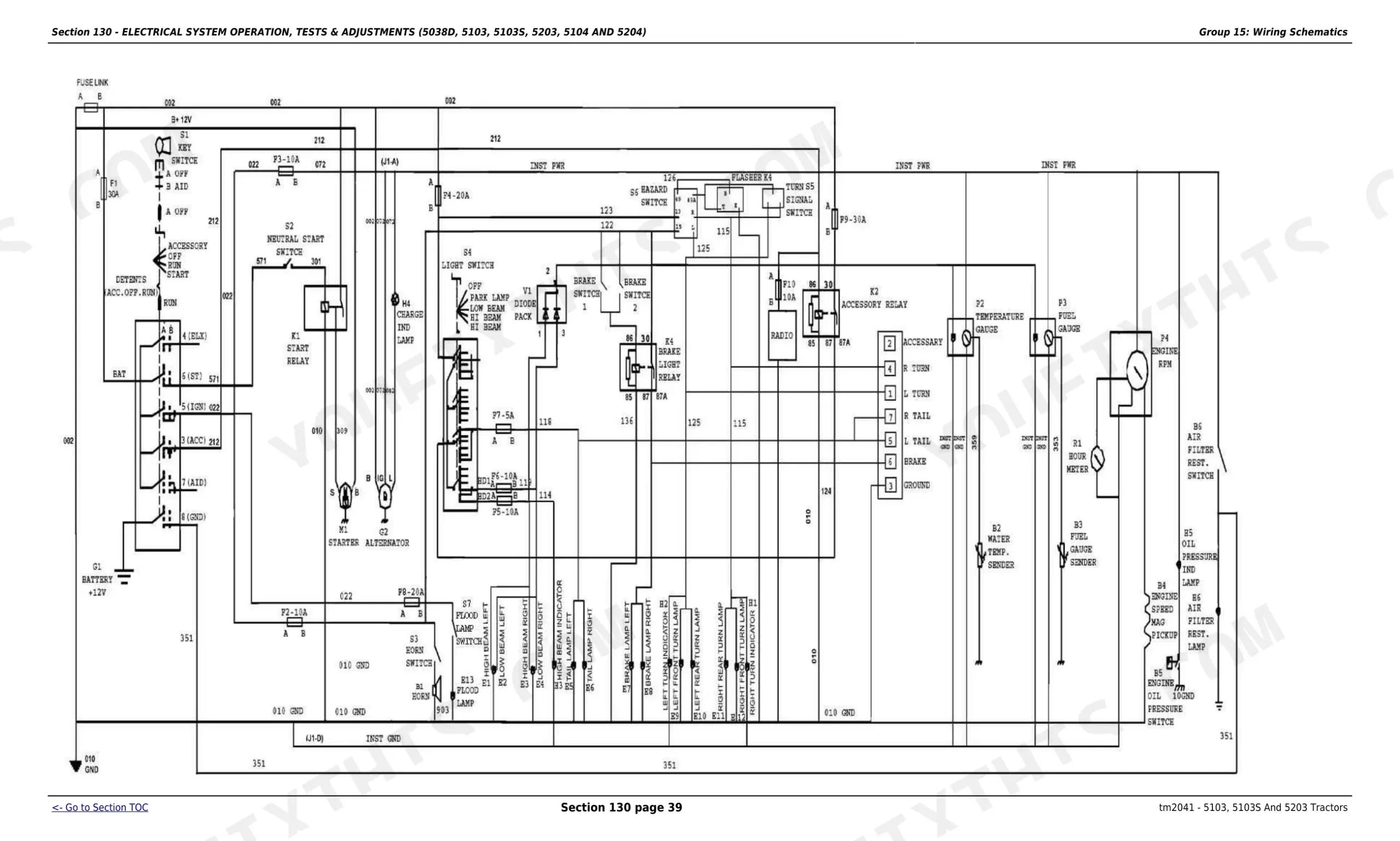
| Electrical System Operation, Tests & Adjustments (5038D, 5103, 510 | 918-1042 | Component Location (Component Location Information, Engine Electrical Components, Right Hand Side, Left Hand Side, Dash and Center Control Console Electrical Components) |
| Electrical System Operation, Tests & Adjustments (for 5103E) | 1043-1137 | Component Location (Component Location Information, Engine Electrical Components, Right Hand Side, Left Hand Side, Dash and Center Control Console Electrical Components) |
| Power Train Operation, Tests & Adjustments | 1138-1254 | Component Location, 'aa' Power Train (Component Location Information, Power Train Components, Dual Clutch Components, Single Clutch Components, Transmission Components, Final Drive Components) |
| Steering and Brake Operation, Tests & Adjustments | 1255-1290 | Component Location (Component Location Information, Steering System Components, Brake System Components) |
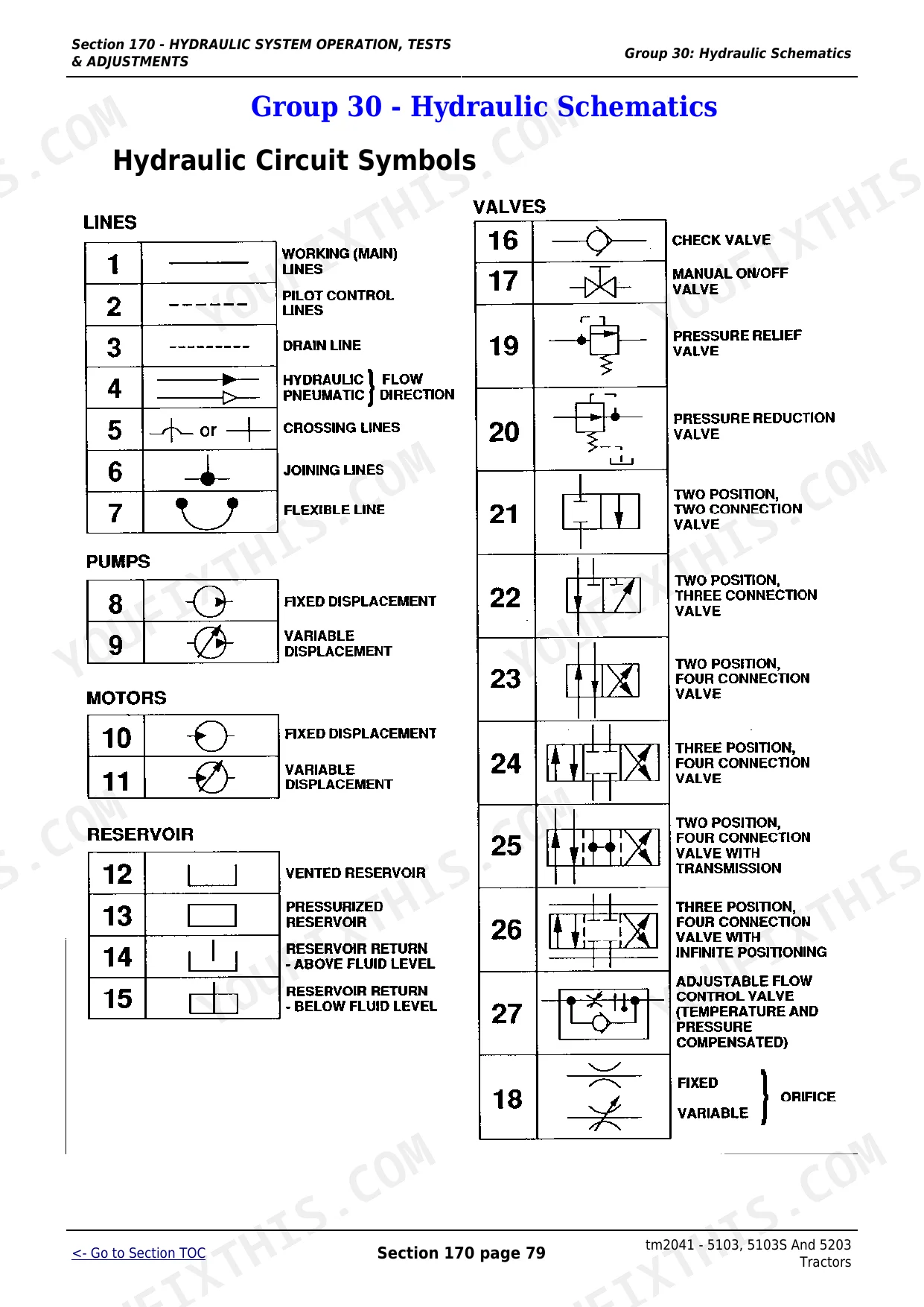
| Hydraulic System Operation, Tests & Adjustments | 1291-1370 | Component Location (Component Location Information, Hydraulic System Components) |
Quick Reference Specifications
| Specification | Value | Page |
|---|---|---|
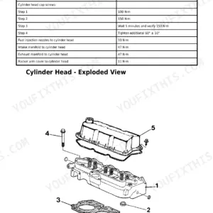
| Cylinder head cap screws (Step 1) | 100 N·m (75 lb-ft) | p. 108 |
| Cylinder head cap screws (Step 2) | 150 N·m (110 lb-ft) | p. 108 |
| Fuel filter assembly to bracket torque | 35 Nm | p. 309 |
| Fuel filter element replacement interval (primary) | 250 hours | p. 307 |
| Air cleaner restriction switch closing vacuum | 4.98–7.48 kPa (20–30 in. H₂O) | p. 946 |
| Air cleaner restriction sensor torque | 4 N·m (40 lb-in.) | p. 329 |
| Oil cooler adapter in cylinder block torque | 40 N·m | p. 253 |
| Pick-Up Screen Cover cap screws torque | 23 N·m (204 lb-in.) | p. 659 |
| Hydraulic Oil Filter cap screws torque | 70 N·m (52 lb-ft) | p. 659 |
| Battery voltage | 12 V | p. 26 |
| Battery capacity | 88 Ah | p. 26 |
| Starter power | 12 V, 2.5 kW | p. 26 |
John Deere 5038–5204 Common Problems This Manual Covers
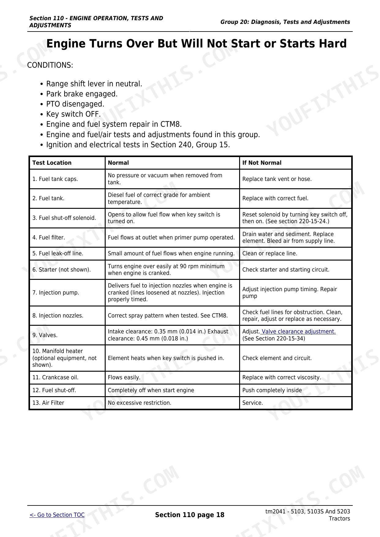
Hard starting after sitting
These tractors commonly crank but fail to start after sitting, usually from clogged fuel filters or air trapped in the fuel system. The Fuel and Air Repair section covers filter replacement, bleeding, and injection pump service to restore fuel delivery.
Manual Section: Section 30 - Fuel and Air Repair p. 299Overheating under load
Temperature climbing quickly during heavy work often traces to low coolant, a blocked radiator, or a fan and belt problem. The Engine Repair section covers the cooling system so you can inspect and service the water pump, thermostat, and related parts.
Manual Section: Section 20 - ENGINE REPAIR p. 77Weak or slow hydraulics
Loader and three point response that is weak, slow, or jerky usually points to low hydraulic oil, a clogged pick-up screen or filter, or a worn pump. The Hydraulic Repair section covers pump removal, inspection, and filter service.
Manual Section: Section 70 - Hydraulic Repair p. 658Clutch or transmission trouble
Hard shifting, gear grinding, or a tractor that will not move after the clutch releases points to clutch adjustment, linkage, or internal transmission wear. The Power Train Repair section covers the clutch housing, transmission, and final drives.
Manual Section: Section 50 - Power Train Repair p. 359Charging and starting faults
Intermittent starting or a battery that will not stay charged usually comes down to the battery, starter, alternator, or wiring. The Electrical Repair section covers battery, starter, and alternator removal, testing, and replacement.
Manual Section: Section 40 - Electrical Repair p. 319Power loss and excessive smoke
Loss of power under load with heavy smoke or rough running often means a restricted air intake, fuel restriction, or injector wear. The Fuel/Air Operation, Tests and Adjustments section walks through diagnosis before any teardown.
Manual Section: Section 120 - Fuel/Air Operation, Tests and Adjustments p. 895Heavy steering or fluid leaks
Increased steering effort or leaks around the steering cylinder point to worn seals or hydraulic steering line problems. The Steering and Brake Repair section covers the steering valve, cylinder, and mechanical steering gearbox service.
Manual Section: Section 60 - Steering and Brake Repair p. 587Frequently Asked Questions
Which tractor models does this manual cover?
This is John Deere technical manual tm2041, covering the 5038D, 5103, 5103E, 5103S, 5104, 5203, and 5204 tractors, all using the 3029D naturally aspirated diesel engine. Repair and diagnostic procedures are shared across the family, with model-specific notes called out where the tractors differ.
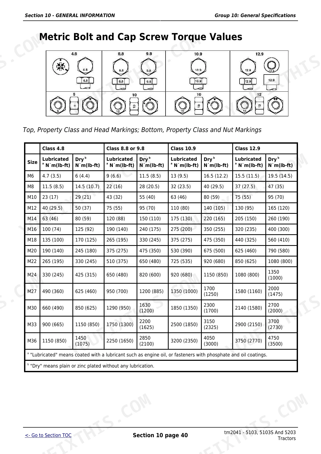
Does it give engine torque specifications?
Yes. The Engine Repair section lists torque values by component group, including the cylinder head cap screws at 100 N·m, then 150 N·m, plus a final 60 degree turn. Metric and inch torque charts are also included in the General Information section. p. 77
How often do the fuel filters need replacing?
The Fuel and Air Repair section covers filter service, with the primary fuel filter element on a 250 hour interval and the secondary on 500 hours. It also gives the fuel filter assembly mounting torque and the remove and install steps for the filter and fuel tank. p. 299
Does it cover wiring and electrical diagnostics?
Yes. The Electrical Repair section covers battery, starter, and alternator service, and separate operation and test sections handle wiring schematics and diagnostics, with dedicated electrical coverage for the 5103E apart from the other models. p. 319
Is this John Deere 5038D & variants Technical Manual a digital download?
Download the full 1370-page searchable Technical Manual for the 5038D and its variants right after checkout. Open it on any device: laptop at the desk, phone out in the field.
Am I able to print pages from this John Deere 5038D & variants manual?
Yes. Print as many copies as you like; there are no restrictions. Plenty of mechanics print just the section they need and carry it to the shop floor.
Does this John Deere 5038D & variants Technical Manual have electrical diagrams?
Yes. You'll find full electrical schematics with wire routing diagrams, connector identification, and circuit descriptions.


Reviews
There are no reviews yet.