


Part of the John Deere Repair Manuals.
This is the John Deere factory diagnostic manual (TM608719) for the 6100D, 6110D, 6115D, 6125D and 6130D tractors covering Tier 0 through Tier 3/Stage IIIA machines (S.N. 060000 and up). Across 1,345 pages it walks through every electronic control unit on the tractor - the Chassis Control Unit (CCU), Engine Control Unit (ECU), Instrument Cluster Control (ICC) and Power Train Reverser (PTR) - with the full DTC code list and step-by-step diagnostic routines for each fault. Beyond the trouble codes, the manual includes complete electrical schematics for 32 named sub-circuits (SE1 through SE32), hydraulic schematic sets and pump flow test procedures with specification tables, drive system and transmission calibration procedures, and the special tools list. It is written for an experienced technician and is the same document a John Deere dealer uses to isolate a fault from first symptom to confirmed repair.
What's Inside This John Deere 6100D-6130D Manual
| System | Pages | Key Topics |
|---|---|---|
| General Information | Safety, General References, Technical Specific References, Glossary of Terms | |
| Diagnostic Trouble Codes | Ccu Code Diagnostics, ECU Code Diagnostics, Icc Code Diagnostics, Ptr Code Diagnostics | |
| Observable Symptoms and System Diagnostics | Engine Diagnostics, Fuel/Air/Exhaust/Cooling Diagnostics, Electrical Diagnostics, ECU Diagnostics, Drive and Transmission Diagnostics, Steering and Brakes Diagnostics, Hydraulic Diagnostics, Cab Diagnostics | |
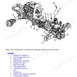
| Engine | Engine Calibrations and Preliminary Checks, Theory of Operation, Engine Schematics, Component and Connector Information, Tests and Adjustments | |
| Fuel, Air Intake, Exhaust and Cooling | Calibrations and Preliminary Checks, Theory of Operation, Schematics, Component and Connector Information, Tests and Adjustments | |
| Electrical System | Theory of Operation, Schematics (SE1-SE32: Starter/Alternator, Neutral Start, Lighting, A/C, Icc, Ehc, ECU, CAN Bus), Components and Connectors, Fuses/Relays/Ground Points/Wiring Harnesses, Tests and Adjustments | |
| Electronic Control Units | Ccu - Chassis Control Unit, ECU - Engine Control Unit, Icc - Instrument Cluster Control, Ptr - Power Train Reverser, Calibrations, Schematics, Tests and Adjustments | |
| Drive Systems and Transmissions | Calibrations and Preliminary Checks, Theory of Operation, Schematics, Component Information, Tests and Adjustments | |
| Steering and Brakes | Brake Calibrations and Checks, Steering Calibrations, Theory of Operation, Schematics, Tests and Adjustments | |
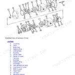
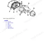
| Hydraulics | Calibrations and Preliminary Checks, Theory of Operation, Hitch Theory, Mid-Mount SCV Theory, Rear SCV Theory, Trailer Brake Theory, Schematics, Tests and Adjustments | |
| Cab and Operator's Station | - | |
| Special Tools | General References, Dealer Fabricated Tools, Service Tools |
Quick Reference Specifications
| Specification | Value | Page |
|---|---|---|
| 6100D, 6110D, 6115D, 6125D, 6130D (Tier 3/Stage IIIA) | ||
| Engine Model | PowerTech 4045 (4.5L), rated below 130 kW (174 hp) | |
| All models | ||
| Hydraulic Main Relief Valve Pressure | 19000-19700 kPa (190-197 bar / 2755-2855 psi) | |
| Hitch Relief Valve Setting | 230-240 bar (3335-3480 psi / ~22000-24000 kPa) | |
| Transmission Pump Min Flow at 38C (100F), 2000 rpm | 28.7 lpm (7.6 gpm) at 15000 kPa (150 bar) test pressure | |
| Hydraulic Oil Temperature for PTR Calibration | 55-70 degrees C (131-158 degrees F) | |
| Alternator Output Voltage | 14.2-14.8 VDC at 2400 rpm | |
| Models with triple pump option | ||
| Triple Hydraulic Pump - Implement Rating | 75.7 lpm (20.0 gpm) | |
| Triple Hydraulic Pump - Steering and Transmission Rating | 29.9 lpm (7.9 gpm) each | |
| All models with PTR transmission | ||
| Transmission Forward/Reverse Clutch Engaged Pressure | 2100 kPa (21 bar / 304-305 psi) | |
John Deere 6100D-6130D Common Problems This Manual Covers
CCU 000110 coolant temperature code sets and engine power is reduced
The CCU logs this code when the coolant temperature sensor voltage is out of normal range (out of range high = open circuit, out of range low = short to ground). Before replacing the sensor, perform the CCU sensor voltage test referenced in the code's diagnostic routine to confirm whether the fault is in the sensor, the harness, or the CCU sensor supply circuit. Check connector integrity at the sensor and at the CCU before condemning any component, since a corroded connector pin is a common cause on these tractors.
Manual Section: Diagnostic Trouble Codes - CCUPTR clutch pressure code sets and tractor defaults to neutral on every shift
PTR pressure sensor codes (PTR 000761, 000763, 521237, 521238) point to forward or reverse clutch pressure that is out of range or reading zero when the clutch should be engaged. The diagnostic routine starts with verifying that the transmission enable valve energizes (expect 1200 kPa / 12 bar at the enable port) and that forward/reverse clutch pressure reaches 2100 kPa (21 bar / ~305 psi) when commanded. If pressure is absent, trace the hydraulic circuit to the enable valve and clutch solenoids before suspecting the PTR control unit itself.
Manual Section: Diagnostic Trouble Codes - PTRHydraulic pump flow is below specification on all SCVs and hitch feels weak under load
Follow the implement pump flow test in the Hydraulics section to confirm low flow at 15000 kPa (150 bar / 2176 psi) test pressure. If flow is below 28.7 lpm (7.6 gpm) at 2000 rpm even at the pump outlet, the implement pump itself is worn or the clipper valve is stuck open. If flow is normal at the pump outlet but low at the SCVs, the diagnostic routine directs you to inspect the mid-mount SCV elbow fitting at the PB port and then the individual SCV spools for leakage or restriction before pulling the pump.
Manual Section: Observable Symptoms - Hydraulic DiagnosticsICC 000167 alternator voltage below normal code sets and battery discharges during operation
ICC 000167 fires when alternator output drops below 9V as seen by the instrument cluster. The electrical tests section checks for 14.2-14.8 VDC at the alternator output terminal at 2400 rpm. If output is low, inspect the alternator charge line and ground path before replacing the unit - a loose or corroded B+ terminal on the alternator is a common cause, and a dragging belt that slips at higher loads will also pull output voltage down under field conditions.
Manual Section: Observable Symptoms - Electrical DiagnosticsFrequently Asked Questions
How do I read and clear diagnostic trouble codes on a John Deere 6100D or 6130D?
Use the Instrument Cluster Control (ICC) monitor to recall and clear active codes. The manual covers the full procedure under the DTCs section: retrieve active codes, record them, then perform the indicated diagnostic routine (sensor voltage test or component check) before clearing. Clearing without completing the diagnosis usually results in the code returning after a short run cycle.
What does a PTR code mean on my John Deere 6100D-6130D tractor?
PTR codes come from the Power Train Reverser control unit, which manages the forward/reverse shuttle transmission. Common PTR faults point to clutch pressure sensor voltage out of range, a stuck enable valve, low system voltage, or a clutch pedal signal conflict. The manual lists each code with its cause and a step-by-step diagnostic routine including the correct test pressures and voltage specifications to isolate the failed component.
How do I test hydraulic pump flow on a John Deere 6100D through 6130D?
The hydraulic section covers the implement pump flow test and the transmission/steering pump flow test. Connect a flow meter, heat the oil to 38 degrees C (100 degrees F), set test pressure to 15000 kPa (150 bar / 2176 psi), and check flow at 1000, 1500 and 2000 rpm. Minimum spec at 2000 rpm is 28.7 lpm (7.6 gpm) for the transmission and steering pumps; the implement pump is rated at 75.7 lpm (20.0 gpm) at full rated speed.
What CCU codes are common on the John Deere 6100D-6130D and what causes them?
Common CCU faults include CCU 000096 (fuel level sensor voltage high or low), CCU 000110 (engine coolant temperature sensor out of range), CCU 001638 (hydraulic oil temperature high), CCU 001883 (rear PTO overspeed or underspeed), and CCU 523316 (switched supply voltage low). Each code lists its exact cause - such as a sensor short, open circuit, or voltage supply fault - and the diagnostic routine points to the specific sensor test or wiring check needed to confirm the failed part.
What hydraulic oil temperature is required before performing a PTR transmission calibration?
The Power Train Reverser calibration requires hydraulic oil to be between 55-70 degrees C (131-158 degrees F) before starting the calibration sequence. Running the calibration with cold oil is one of the most common reasons the procedure fails or produces inaccurate clutch pressure settings, leading to rough shuttle shifts or clutch slippage in the field.
What format is this manual in?
This is a 1345-page searchable PDF (62 MB) ready for immediate download. Works on any device, so pull it up on your phone while you're under the hood. No shipping, no waiting.
Can I print specific sections of this John Deere 6100D, 6110D, 6115D, 6125D?
Absolutely. No DRM or copy protection. Print the whole manual or just the pages you need. Any home or office printer works.


Reviews
There are no reviews yet.