


Part of the John Deere Repair Manuals.
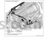
All 1,612 pages of this John Deere 6 Series Repair Manual (OEM #TM405819) target one job: getting your 6105M, 6115M, 6125M, 6130M, or 6140M tractor back to factory spec. You get step-by-step reconditioning procedures for every major system (engine, drivetrain, brakes, hydraulics, operator cab), detailed exploded views, fluid capacity tables, diagnostic trouble codes, and a full troubleshooting section. Open to the drivetrain section and you'll find separate rebuild procedures for all four transmission variants: PowrQuad Plus, AutoQuad Plus, PowrReverser, and SyncroPlus, each with special tool lists and repair specifications. Set the front engine mount-to-block screws to 220 N·m (162 lb.-ft.) and your DPF clamp (A) to 15-25 N·m. No more chasing numbers across forums. Bookmarked and searchable by keyword; open it on any device and start wrenching.
What's Inside This John Deere 6105M–6140M Series Repair Manual
| System | Pages | Key Topics |
|---|---|---|
| Safety | 8-62 | Group 05 - Safety Measures (Recognize Safety Information, Understand Signal Words, Follow Safety Instructions, Prevent Machine Runaway, Operating the Tractor Safely, Operating the Loader Tractor Safely, Passenger Seat, Use Safety Lights and Devices, Towing Trailers/Implements Safely, Use Caution on Slopes and Uneven Terrain, Freeing a Mired Machine, Avoid Backover Accidents, Handle Fluids Safely, Avoid Fires, Handling Batteries Safely, Prepare for Emergencies, Avoid High-Pressure Fluids, Service Cooling System Safely, Remove Paint Before Welding or Heating, Avoid Heating Near Pressurized Fluid Lines, Work in Ventilated Area, Avoid Contact with Agricultural Chemicals, Handle Agricultural Chemicals Safely, Stay Clear of Rotating Drivelines, Wear Protective Clothing, Protect Against Noise, Practice Safe Maintenance, Avoid Hot Exhaust, Exhaust Filter Cleaning, Clean Exhaust Filter Safely, Read Operator Manuals for Isobus Implements, Use Steps and Handholds Correctly, Use Seat Belt Properly, Park Machine Safely, Use Proper Lifting Equipment, Construct Dealer-Made Tools Safely, Support Machine Properly, Work in Clean Area, Illuminate Work Area Safely, Service Machines Safely, Service Accumulator Systems Safely, Service Tires Safely, Use Proper Tools, Service Front-Wheel Drive Tractor Safely, Avoid Eye Contact with Radar, Keep ROPS Installed Properly, Replace Safety Signs, Dispose of Waste Properly, Live with Safety, Safety Measures on Electronic Control Units, Servicing Electronic Control Units, Welding Near Electronic Control Units, Keep Electronic Control Unit Connectors Clean, Safety Instructions for Replacing a Halogen Bulb, Safety Instructions for Replacing Xenon Bulbs and Ballast Units) |
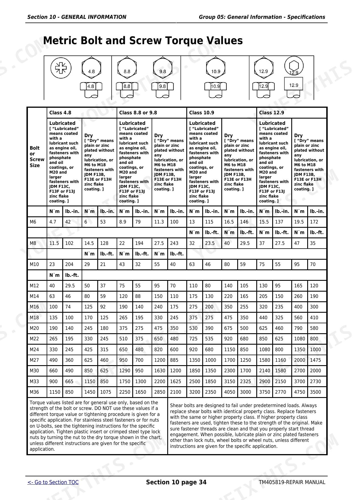
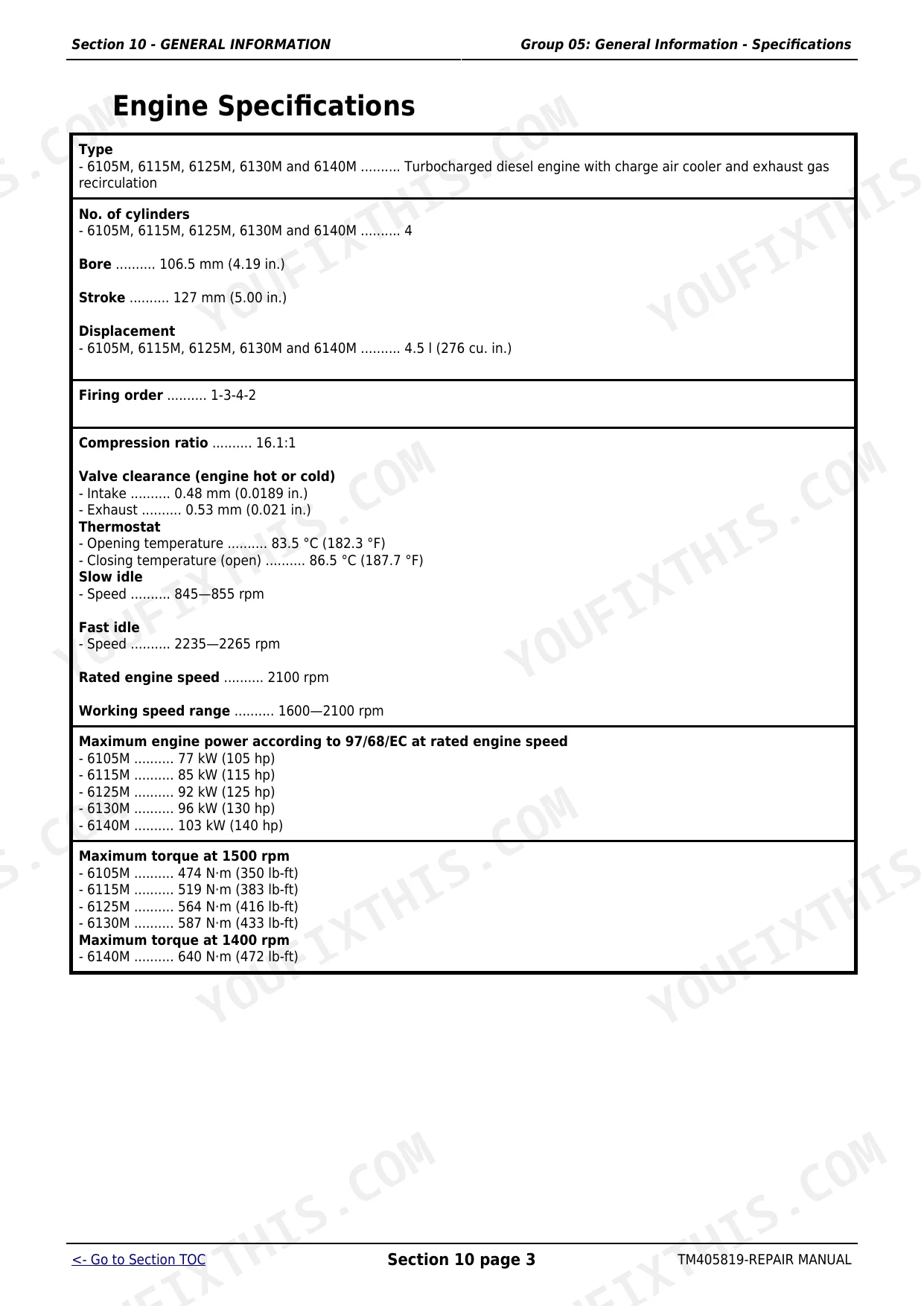
| General Information | 63-116 | Group 05 - General Information - Specifications (Specifications - Summary of References, Engine Specifications, PTO Power Output, PTO Power, Capacities, Air Intake System, Electrical System, Hydraulic System with Axial Piston Pump, Clutch Operation, PowrQuad Plus™ Transmission, AutoQuad Plus™ Transmission, Rear PTO, Front PTO, Differential, Differential Lock, Final Drives, Front-Wheel Drive, FWD Axle with TLS, Cab Suspension, Hydraulic Brakes, Auxiliary Brake, Park Lock, Hitch, Immobilizer, Front Hitch, Ground Travel Speeds, Front and Rear Wheels, Dimensions and Weights, Handling and Storing Diesel Fuel, Diesel Fuel, Minimizing the Effect of Cold Weather on Diesel Engines, Biodiesel Fuel, Lubricity of Diesel Fuel, Diesel Engine Break-In Oil, John Deere Break-In™ Plus Engine Oil, Transmission and Hydraulic Oil, Front-Wheel Drive Axle Oil, Heavy Duty Diesel Engine Coolant, Supplemental Coolant Additives, Grease, Oil Filters, Mixing of Lubricants, Lubricant Storage, Operating in Warm Temperature Climates, Alternative and Synthetic Lubricants, Unified Inch Bolt and Screw Torque Values, Metric Bolt and Screw Torque Values, Hydraulic System Inch Fitting Torques, Hydraulic System Metric Fitting Torques, Product Identification and Component Serial Number Plate, Plate for Product Identification Number, Engine Serial Number, Transmission Serial Number, Front-Wheel Drive Serial Number, Operator′s Cab Serial Number, Operator′s Seat Serial Number, Subassembly Serial Numbers) |
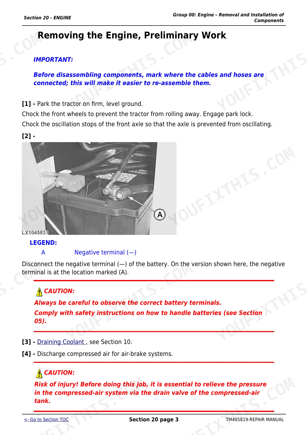
| Engine | 117-154 | Group 00 - Engine – Removal and Installation of Components (Engine - Removal and Installation of Components, Summary of References, Engine - Removal and Installation of Components, Special Tools, Repair Specifications, Removing the Engine, Preliminary Work, Installing the Engine, Additional Work, Engine Mounting, Replacing the Engine Mountings, Replacing the Front Engine Mountings, Replacing the Rear Engine Mountings, Replacing the Engine Mounting, Further Work) |
| Fuel, Air Intake, Cooling and Exhaust System | 155-213 | Group 10 - Fuel System (Fuel System - Summary of References, Fuel Tank, Removal and Installation, Fuel Level Sensor, Bleeding the Fuel System) |
| Electrical System | 214-279 | Group 05 - Electrical System - Connectors (Electrical System -Connector, Summary of References, Special Tools, General, Using High-Pressure Washers, Strip Wire Ends, Install a Terminal, Weather Pack Connectors, Metri Pack Connectors with Terminal Lock at the Rear, Metri Pack Connectors with Terminal Lock at the Front, Metri Pack Connectors, Connectors for Electronic Control Units, Crimp Snap in Connectors, Kostal Connectors, Deutsch Connectors, Individual Terminals) |
| Electronic Control Units | 280-305 | Group 05 - Removal and Installation of Control Units (Electronic Control Units - Summary of References, Instructions When Replacing a Control Unit, Position of the Control Units, Engine Control Unit - Removal and Installation, Central Control Unit - Removing and Installing, Instrument Unit - Removing and Installing, Front Chassis Control Unit - Removing and Installing, Immobilizer Control Unit - Removing and Installing) |
| A - Drive Train (Without Transmission) | 306-608 | Group 00 - Drive Train - Removal and Installation of Components (Drive Train - Removal and Installation of Components, Summary of References, Drive Train - Special Tools, Drive Train - Repair Specifications, Draining transmission/hydraulic Oil, Filling transmission/hydraulic Oil, Removing Final Drives, Installing the Final Drives, Removing the Rear PTO, Installing the Rear PTO, Removing the Front PTO, Installing of the Front PTO) |
| C - Powrquad™ Transmission | 609-631 | Group 00 - PowrQuad™ Transmission - Removal and Installation of Components (PowrQuad™ Transmission - Removal and Installation of Components, Summary of References, PowrQuad™ Transmission - Installation and Removal of Components, Special Tools, PowrQuad™ Transmission - Removal and Installation of Components, Repair Specifications, AutoQuad™ Plus Transmission, Removal and Installation, Removing the PowrQuad™ Transmission - Preliminary Work, Removing the PowrQuad™ Transmission, Installing the PowrQuad™ Transmission, Removing the Range Transmission, Installing the Range Transmission) |
| E - Powrreverser™ Transmission | 632-851 | Group 00 - PowrReverser™ Transmission - Installation and Removal of Components (PowrReverser™ Transmission - Installation and Removal of Components, Summary of References, PowrReverser™ Module - Special Tools, PowrReverser™ Module - Repair Specifications, Remove PowrReverser™ Module - Preliminary Work, PowrReverser™ Transmission - Remove the PowrReverser™ Module, PowrReverser™ Transmission - Install the PowrReverser™ Module, Final Assembly, PowrReverser™ Transmission - Remove the Gear Transmission, PowrReverser™ Transmission - Install the Gear Transmission, PowrReverser™ Transmission - Remove the Range Transmission, PowrReverser™ Transmission - Install the Range Transmission) |
| F - Syncroplus™ Transmission | 852-979 | Group 00 - SyncroPlus™ Transmission - Installation and Removal of Components (Removal and Installation of Components, Summary of References, Special Tools, Repair Specifications, Remove Clutch Housing, Preliminary Work, Install the Clutch Housing, Final Assembly, Install and Remove Gear Transmission.) |
Quick Reference Specifications
| Specification | Value | Page |
|---|---|---|
| All Models | ||
| Engine-mounting screws, rear | 100 N·m (74 lb.-ft.) | p. 118 |
| Front engine support to main frame, mounting screws | 100 N·m (74 lb.-ft.) | p. 118 |
| Engine Bore | 106.5 mm | p. 65 |
| Engine Stroke | 127 mm | p. 65 |
| Cooling System Coolant Change Capacity | 28.2 L | p. 68 |
| Transmission/Hydraulic System Oil Change Capacity | 52 l | p. 68 |
| 6105M, 6115M, 6125M, 6130M | ||
| DPF Clamp (A) torque | 15–25 N·m (11–18 lb-ft) | p. 209 |
| DPF Clamp (B) torque | 28–42 N·m (21–31 lb-ft) | p. 209 |
| 6140M, 6150M, 6170M | ||
| DPF Clamp (A) torque | 15–25 N·m (11–18 lb.-ft.) | p. 204 |
| DPF Clamp (B) torque | 28–42 N·m (21–31 lb.-ft.) | p. 204 |
| 4-cylinder tractors | ||
| Engine Compression Ratio | 16.1:1 | p. 65 |
| 6105M-6140M | ||
| Engine Crankcase Oil Change Capacity (with filter) | 16 l | p. 68 |
John Deere 6105M–6140M Series Common Problems This Manual Covers
John Deere 6105M starter won't turn over in any gear or fails in forward and reverse.
Check the transmission and hydraulic oil level to ensure it meets the 52 l capacity listed on page 68. Inspect the PowrReverser module connections on page 632. Test the neutral start circuit and verify the gear sensor matches the actual transmission position to clear starting failures.
Manual Section: E - Powrreverser™ Transmission p. 632Engine warning light alerts for exhaust filter and DPF regeneration fails after 250 hours.
Remove the diesel particulate filter and inspect for excessive soot buildup. When reinstalling on models 6105M through 6130M, torque DPF clamp A to 15–25 N·m (11–18 lb-ft) as specified on page 209. Verify the engine oil used is Plus-50 II to prevent premature clogging.
Manual Section: Fuel, Air Intake, Cooling and Exhaust System p. 209Transmission and hydraulic system oil overheating warning appears after 15 minutes of heavy loader use.
Drain and refill the transmission and hydraulic system oil to the required 52 l capacity on page 68. Inspect the hydraulic oil filter for restrictions. Verify the TLS accumulator nitrogen pressure is correct and check the cooling system for proper flow to clear high temperature codes.
Manual Section: Hydraulic System p. 68Rear PTO actuation fails or engages erratically due to safety circuit interlock malfunction.
Inspect the PTO safety circuit sensor and wiring harness near the rear axle for damage. If replacing the rear PTO assembly, torque the housing to differential housing bolts to 240 Nm as directed on page 307. Test the actuation to confirm proper engagement and disengagement.
Manual Section: A - Drive Train (Without Transmission) p. 307Frequently Asked Questions
What format is this manual in?
A 1612-page Repair Manual in searchable PDF format, available the moment you complete checkout. View on computer, tablet, or phone, with no shipping wait.
Can I print this manual?
Yes. The PDF has no DRM restrictions, so print any page or section you need for your shop. Works with any standard printer.


Reviews
There are no reviews yet.