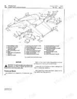
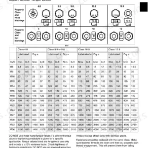
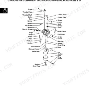
Part of the John Deere Repair Manuals.
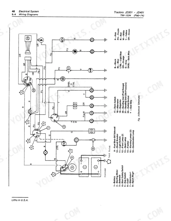
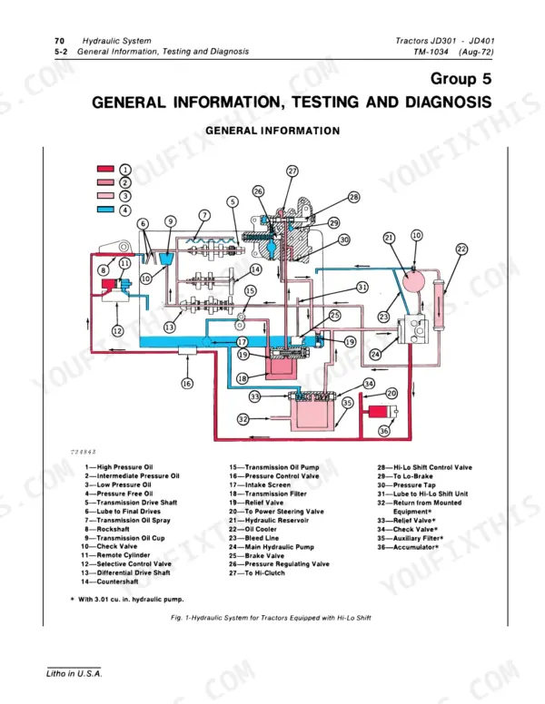
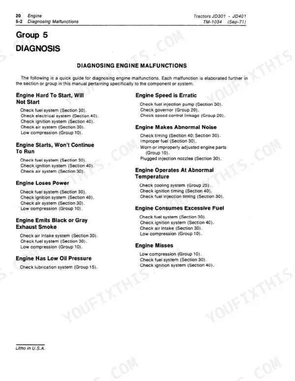
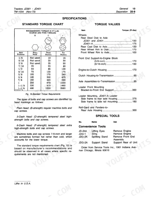
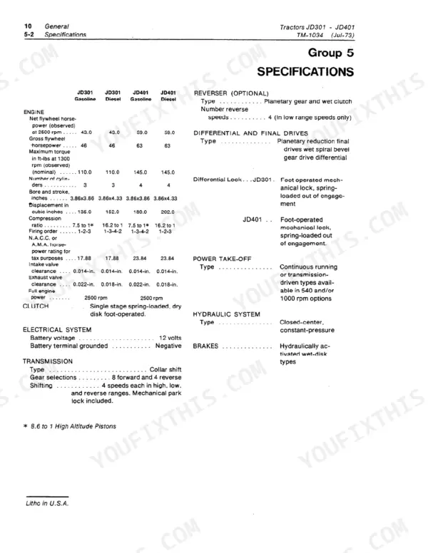
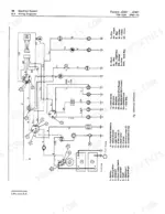
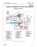
Hunting for a John Deere 301 technical manual PDF straight from the factory? This 344-page Technical Manual (OEM TM-1034, John Deere Dubuque Works) covers the JD301 and JD401 tractors together with the 7310 and JD401-A loaders and the 9250 backhoe, from tune-up and lubrication all the way through full tractor separation. Both engines are documented side by side, so the tables print a value for each: connecting rod cap screws take 65 ft-lbs on the diesel against 45 ft-lbs on the gasoline engine, and exhaust valve clearance is 0.018 in. against 0.022 in. Inside you get the full-machine electrical schematic with its wire-colour routing table and component connector pinouts (pages 94-96), covering the charging, starting, ignition and lighting circuits, plus colour-coded hydraulic system diagrams for both the Hi-Lo Shift and Reverser tractors (pages 226-227) and the rockshaft circuit (page 260). You also get diagnosis charts for the engine, fuel system and power train, with page after page of clutch, transmission, reverser and Hi-Lo shift procedures. Verify your charging output against the 12-volt specs before you condemn a good alternator. Bookmarked by system, this scanned PDF opens on any device; carry your tablet to the machine and start wrenching.
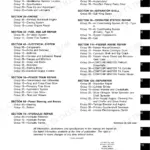
What's Inside This John Deere JD301, JD401, JD401-A Manual
| System | Pages | Key Topics |
|---|---|---|
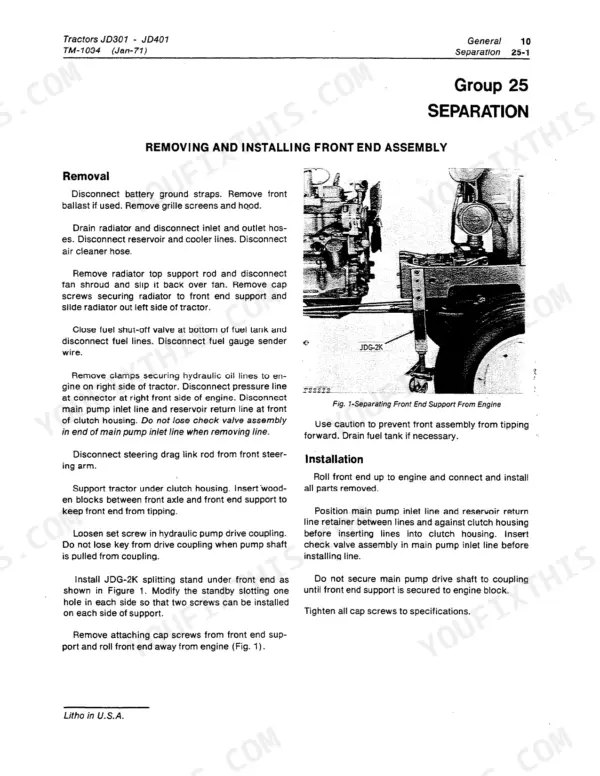
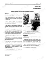
| General | 7-32 | Specifications, Predelivery and After-Sales Services, Tune-Up, Lubrication, Tractor Separation |
| Engine | 33-72 | Diagnosis, Basic Engine, Lubrication System, Governor and Speed Control Linkage, Cooling System, Specifications and Special Tools |
| Fuel System | 73-90 | Diagnosis, Fuel Tank, Transfer Pump and Filters, Air Intake System, Gasoline Carburetor, Diesel Fuel Injection Pump |
| Electrical System | 91-120 | Wiring Diagrams, Charging System, Starting Motor, Ignition System, Gauges and Switches |
| Power Train | 121-200 | Diagnosis, Clutch Assembly, Transmission, Reverser, Hi-Lo Shift Unit, Continuous Running and Transmission-Driven PTO, Independent PTO, Differential, Final Drives |
| Steering and Brakes | 201-224 | Hydraulic Brakes, Manual Steering, Power Steering |
| Hydraulic System | 225-310 | General Information, Testing and Diagnosis, Hydraulic Pump, Hydraulic Components, Rockshaft System, Selective Control Valve, 7310 Loader Control Valve, JD401-A Loader Control Valve, Backhoe Control Valve, Hydraulic Cylinders |
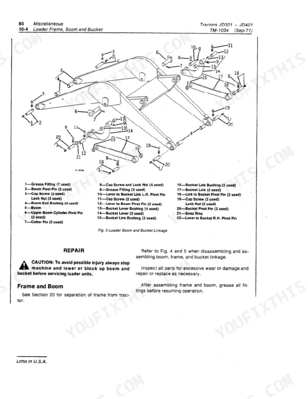
| Miscellaneous Components | 311-332 | Front End Support and Axle Assembly, 7310 Loader Frame, Boom and Bucket, Drott 4-In-1 Bucket, JD401-A Backhoe Frame, Specifications and Special Tools |
| Index | 333-344 | Alphabetical Index |
Quick Reference Specifications
| Specification | Value | Page |
|---|---|---|
| both gasoline and diesel | ||
| Cylinder head bolt torque | 110 ft-lbs | p. 67 |
| Main bearing cap screw torque | 85 ft-lbs | p. 67 |
| Intake valve clearance | 0.014 in. | p. 8 |
| engine-specific | ||
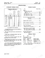
| Connecting rod cap screw torque | 65 ft-lbs (diesel), 45 ft-lbs (gasoline) | p. 67 |
| Exhaust valve clearance | 0.022 in. (gasoline), 0.018 in. (diesel) | p. 8 |
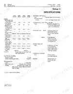
| Compression ratio | 7.5:1 (gasoline), 16.2:1 (diesel) | p. 8 |
| gasoline only | ||
| Spark plug torque | 35 ft-lbs | p. 68 |
| diesel only | ||
| Injection nozzle-to-head torque | 16 ft-lbs | p. 68 |
| JD301 | ||
| Displacement (JD301) | 135 cu in. (gasoline), 152 cu in. (diesel) | p. 8 |
| JD401 | ||
| Displacement (JD401) | 180 cu in. (gasoline), 202 cu in. (diesel) | p. 8 |
| per model | ||
| Net flywheel horsepower at 2500 rpm | JD301: 43.0 hp; JD401: 59.0 hp | p. 8 |
| Fuel tank capacity | JD301: 16-1/2 US gal; JD401: 19-1/2 US gal | p. 9 |
| Engine cooling system capacity | JD301: 2.75 US gal; JD401: 3 US gal | p. 9 |
| All Models | ||
| Electrical system | 12 volts, negative ground | p. 8 |
| Transmission-hydraulic system capacity | 10 US gal | p. 9 |
| Rockshaft thermal relief valve opening pressure | 3500-4500 psi | p. 230 |
| per pump | ||
| Main hydraulic pump stand-by pressure | 2200-2300 psi (0.69 and 1.38 cu in. pumps), 2300-2400 psi (3.01 cu in. pump) | p. 229 |
| Main hydraulic pump minimum flow at 2000 psi | 6 gpm (0.69 cu in.), 11 gpm (1.38 cu in.), 26 gpm (3.01 cu in.) | p. 229 |