


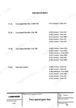
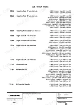
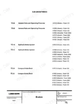
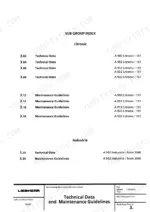
The factory service manual Liebherr issued for the A 900, A 902, A 912, A 922 and A 932 Litronic wheeled excavators, split into nineteen bookmarked repair groups running from safety and service fluids through diesel engines, hydraulics, electrics, swing gear, axles, steering, brakes and the hydraulic tank.
Engine data covers the Deutz BF 4 L 913, the Deutz BF 4 M 1013 E and Liebherr's own diesels. The hydraulic groups walk through operating pressures, pressure checks and relief valve adjustment on the variable displacement double pumps, and the electrical group carries the basic machine schematic plus circuit board and slip ring coverage.
It is a scan of the paper book - no text search, but real PDF bookmarks jump you straight to each group.
What's Inside This Liebherr A900 to A932 Litronic Manual
| System | Pages | Key Topics |
|---|---|---|
| Read Me and Front Matter | 1-4 | Read Me, Manual Structure |
| Group 1 - General Information | 5-48 | Safety Guidelines, Charts and Norms, Repair Welding, Service Fluids, Recommended Lubricant List |
| Group 2 - Tools | 49-140 | Special Tools for Excavators, Electrical Connections, Tools for Liebherr and Deutz Diesel Engines, Hydraulic Component Tools |
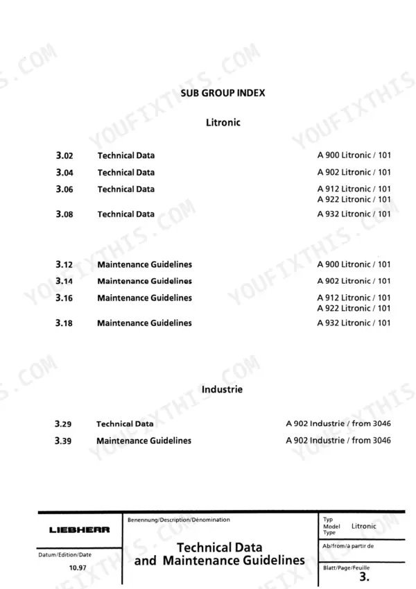
| Group 3 - Technical Data and Maintenance Guidelines | 141-198 | Technical Data, Maintenance Guidelines |
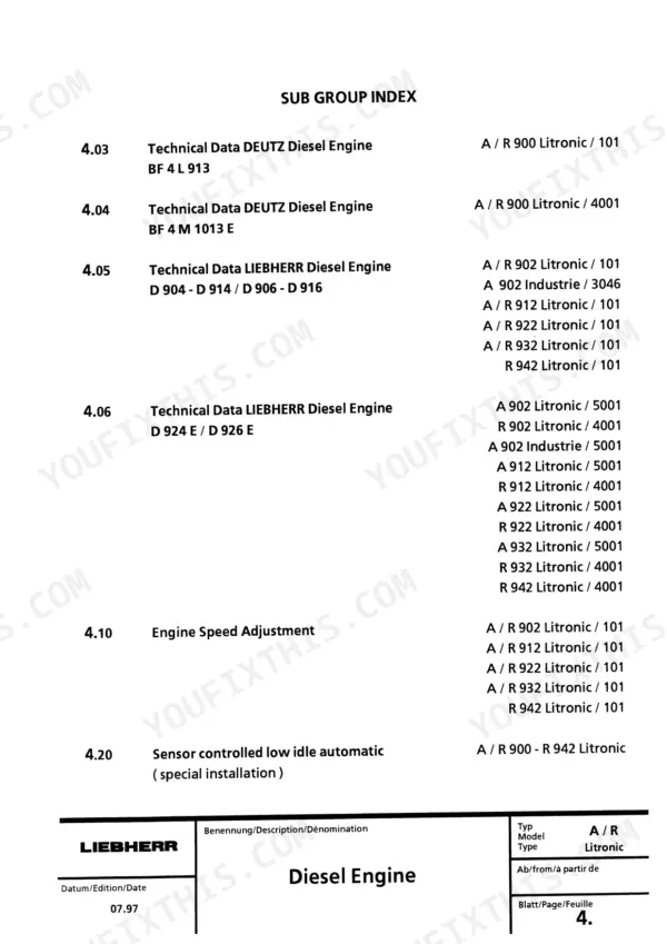
| Group 4 - Diesel Engine | 199-224 | Technical Data Deutz BF 4 L 913, Technical Data Deutz BF 4 M 1013 E, Technical Data Liebherr Diesel Engines |
| Group 5 - Coupling | 225-242 | Coupling, Pump Distributor Gear |
| Group 6 - Hydraulic System | 243-440 | Operating Pressures, Pressure Check and Adjustments, Hydraulic System Components |
| Group 7 - Hydraulic Components | 441-734 | Variable Displacement Double Pumps, Swing Pumps, Hydraulic Motors, Hydraulic Cylinders, Control Valves |
| Group 8 - Electrical System | 735-1062 | Basic Machine Electrical Systems, Special Installations, Circuit Boards, Slip Ring |
| Group 9 - Swing Gear and Swing Brake | 1063-1100 | Swing Gear Liebherr SAT, Swing Brake |
| Group 10 - Swing Ring | 1101-1110 | Swing Ring Construction and Function |
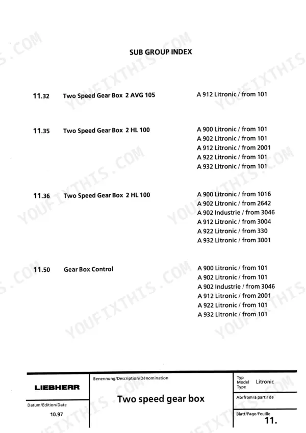
| Group 11 - Two Speed Gear Box | 1111-1168 | Two Speed Gear Box 2 AVG 105, Two Speed Gear Box 2 HL |
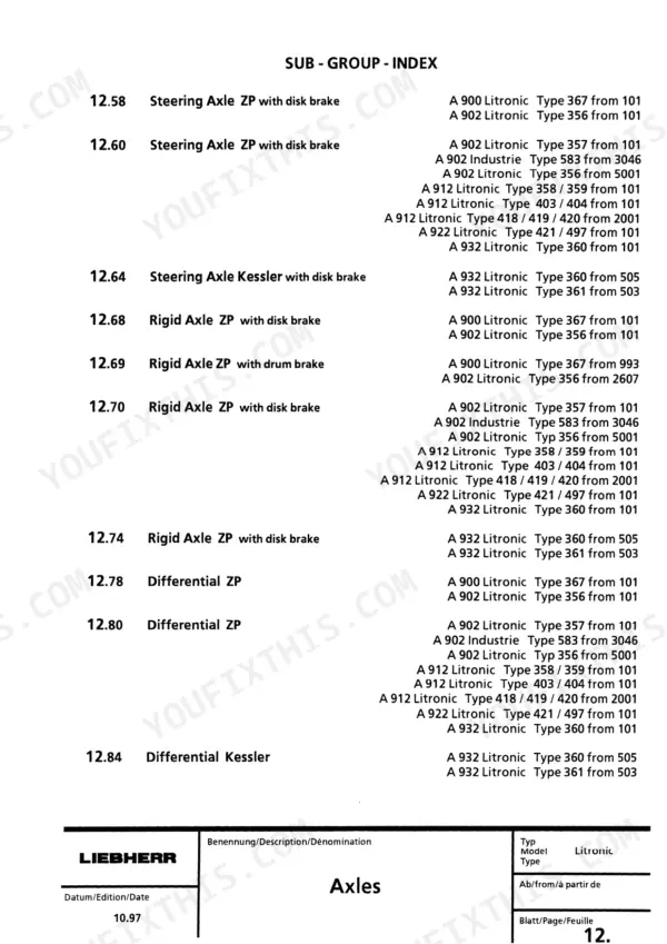
| Group 12 - Axles | 1169-1282 | Steering Axle ZP with Disk Brake, Steering Axle Kessler with Disk Brake |
| Group 13 - Steering | 1283-1320 | Hydrostatic Steering, Servostat, Steering Cylinder, Flow Indicator |
| Group 14 - Oscillating Axle Stabilizer | 1321-1356 | Oscillating Axle Stabilizer, Stabilizing Cylinder |
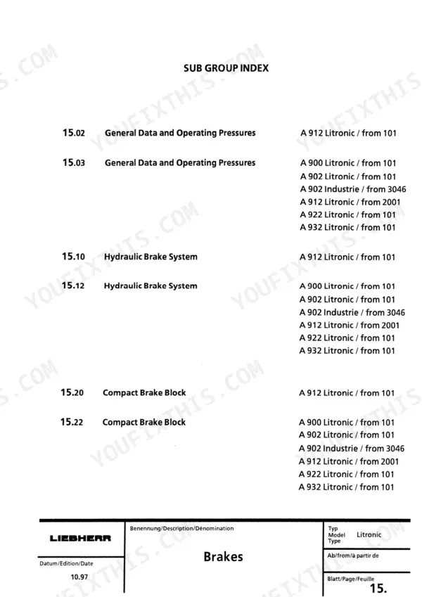
| Group 15 - Brakes | 1357-1400 | General Data and Operating Pressures, Hydraulic Brake System, Compact Brake Block |
| Group 16 - Special Installations and Hydraulic Installation Kits | 1401-1714 | Overload Warning Devices, Hydraulic Installation Kits |
| Group 17 - Cab, Heater and Ventilation System | 1715-1782 | Heater D 1 L C, Heater D 3 L C, Supplementary Heater, Ventilation |
| Group 18 - Undercarriage and Uppercarriage Attachments | 1783-1798 | Combinations, Expander Bolt |
| Group 19 - Tank Configuration | 1799-1806 | Tank System Design and Function, Hydraulic Tank |
Quick Reference Specifications
| Specification | Value | Page |
|---|---|---|
| Basic machine weight with 2 Pt. outriggers (type 367 101) | 11,7 t | |
| Weight with backhoe attachment (2 Pt. outriggers) (type 367 101) | 14,9 t | |
| Length with adj. attachment/travel position (type 367 101, 367 901) | 5900 mm | |
| Width, total (type 367 101, 367 901) | 2500 mm | |
| Height, total without attachment (type 367 101, 367 901) | 3153 mm | |
| Ground clearance (type 367 101, 367 901) | 370 mm | |
| Digging force on tooth/breakout force (type 367 101, 367 901) | 76,0/82,2 KN | |
| Total drawbar pull (in off road gear and max. operating pressure) (type 367 101, 367 901) | 78,2 KN | |
| Engine Type (type 367 101) | DEUTZ BF 4 L 913 LK 49 |
Liebherr A900 to A932 Litronic Common Problems This Manual Covers
Cab functions, display and swing/boom controls intermittently dead while the engine still runs
Start with the basic machine schematic in Group 8 - Electrical System, laid out in numbered circuit columns, then work the circuit board and slip ring sections. Most of these intermittent failures trace to corroded connectors or the slip ring between upper and undercarriage, not the boards themselves.
Manual Section: Group 8 - Electrical System p. 340Hydraulic pump whine or abnormal pump noise under load
Before condemning the pump, use Group 3 - Technical Data and Maintenance Guidelines to rule out low oil and a clogged filter, then bleed air from the suction side. If the whine stays, Group 7 strips the variable displacement double pumps so you can measure wear and make a proper verdict.
Manual Section: Group 7 - Hydraulic Components p. 876Weak or slow hydraulics - machine moves but has no power in the dig
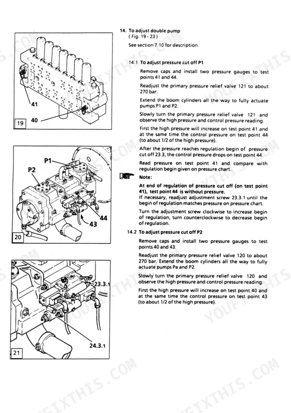
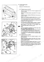
Group 6 - Hydraulic System walks the pressure check step by step: install gauges on test points 40, 41, 43 and 44, then readjust primary pressure relief valves 120 and 121 to about 270 bar. Twenty minutes on the gauges tells you whether the pumps or the relief valves are at fault.
Manual Section: Group 6 - Hydraulic System p. 1169Swing gear noise, jerky slewing or a swing brake that will not release cleanly
Group 9 covers the Liebherr SAT swing gear and the swing brake as separate sections with construction, function and repair coverage, while Group 7 handles the hydraulic motor driving it. Check brake release pressure first - a dragging swing brake mimics a worn gear and costs nothing to rule out.
Manual Section: Group 9 - Swing Gear and Swing Brake p. 1357Frequently Asked Questions
The display goes blank and my boom and swing controls die while the engine keeps running. Will this manual help?
This is the classic complaint on these machines, and it is electrical, not hydraulic. Group 8 covers the basic machine electrical systems, circuit boards, special installations and the slip ring, with the schematic laid out in numbered circuit columns so you can trace each function wire by wire. Nine times out of ten the fault is a corroded connector or the slip ring between the upper and undercarriage, and the schematic is how you prove it before spending money on a board. p. 199
How do I reset error code E 610 on an A 900 Litronic?
There is no reset button on these - the code clears when the underlying fault clears. I will be straight with you: I cannot promise this book prints a fault code lookup table. What it does give you is the Group 8 electrical schematic in numbered circuit columns plus the circuit board documentation, which is what you actually need to find the sender, wire or connector throwing the code in the first place. p. 876
Can I check and adjust the hydraulic pressures myself?
Yes, and it is one of the strongest parts of the book. Group 6 has you install gauges on test points 40, 41, 43 and 44 and readjust the primary pressure relief valves 120 and 121 to about 270 bar for the double pump pressure cut-off. You need a set of pressure gauges and the right test fittings, but the procedure itself is step by step and doable in the yard. p. 340
Which engines does this manual cover? My machine has a Deutz.
Group 4 gives technical data for the Deutz BF 4 L 913, the Deutz BF 4 M 1013 E and the Liebherr diesel engines, so both the Deutz-powered and Liebherr-powered machines in this series are in scope. Group 2 also lists the special tools for both Liebherr and Deutz diesels. Check your engine plate before ordering parts - these models ran with different engines depending on build. p. 1111
Does it include a full hydraulic schematic?
This book does not carry a hydraulic circuit diagram. The hydraulic groups carry operating pressures, pressure check and adjustment procedures, and component-level coverage of the double pumps, swing pumps, motors, cylinders and control valves instead. Electrical schematics are present. If your job is setting pressures or rebuilding a pump you are covered; if you need a full oil-flow circuit drawing, this is not the document for that. p. 243


Reviews
There are no reviews yet.