

The factory service manual for the Liebherr A 900 C, A 904 C, A 914 C and A 924 C Litronic EDC wheeled excavators, order no. 10216479, edition 09/2004 with updates through 09/2010.
Eighteen groups run from the D 934 diesel and DPVO 165 variable-displacement pump through the LSC hydraulic system, 2 HL 290 two-speed gearbox, MS-E 3060 steering axle, swing gear and brake, oscillating axle support, brakes, cab heater/AC and central lubrication. You get model-specific pressure adjustment protocols with measuring point locations, 21 A3 fold-out hydraulic circuit sheets, colour wiring diagram sheets by electrical kit, and the service level menus for the BBT/DISP2 display and the Datalogger.
This is the book the dealer techs work from.
What's Inside This Liebherr A 900 C, A 904 C, A 914 C, A 924 C Litronic EDC Manual
| System | Pages | Key Topics |
|---|---|---|
| Front Matter and Chapter Index | 1-8 | Document Identification, Order No. 10216479, Edition and Update History, Chapter Index, Manufacturer Details |
| Group 1 - General Information | 9-116 | Changes and Modifications to Series, Approved Lubricants and Fuels, Oil Supplier Approval Tables, Change Marks, Safety and Handling Guidelines |
| Group 2 - Tools | 117-170 | Special Tools General Information, Special Tools for Electrical Equipment, Assembly Tools for Hydraulic Cylinders, Special Tools for Hydraulic Systems, Special Tools for Axles (ZF), Crimp Tool |
| Group 3 - Technical Data and Maintenance Guidelines | 171-714 | Checking and Adjusting Tasks, Measuring Points and Locations, Value Measured Records, Test Current, Type Overview a 904 C LI, Type 1002 Data |
| Group 4 - Engine | 715-820 | Technical Data of Diesel Engines, Bleeding the Fuel System, Datalogger Software Version 2.3.09, Datalogger Settings Menu, Datalogger Software Update, Pressure Offset |
| Group 5 - Clutch and Splitterbox | 821-834 | Pump Distributor Gear, Design and Function of Coupling, Coupling Torsion Damper, Dismantling and Installing the Coupling, Variable-Displacement Pump, Oil Filler Neck and Dipstick |
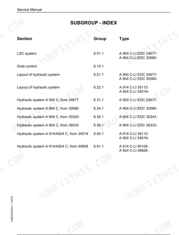
| Group 6 - Hydraulic System | 835-930 | Layout of Hydraulic System, LSC System, Hydraulic Circuit Diagrams, Secondary Pressure-Relief Valve, Restrictor Check Valve, Shuttle Valve, Pressure-Relief Bleeder Valve, Hydraulic Tank |
| Group 7 - Hydraulic Components | 931-1252 | LSC Control Valve Block, LSC Pilot Plate, DMVA Regulating Motor (Travel Drive), Hydraulic Double Plunger Cylinder, Secondary Pressure-Relief Valve, Technical Data |
| Group 8 - Electrical System | 1253-1980 | Overview of Electrical Symbols, Arrangement of Components, Right Console, BBT/DISP2 Display, Service Level and Machine-Specific Settings, Directory of Electrical Kits, Wiring Diagrams of Kits |
| Group 9 - Swing Gear | 1981-2010 | Slewing Gear Mechanism, Slewing Gear Brake, Positioning Slewing Brake, Repair of Brake, Functional Description |
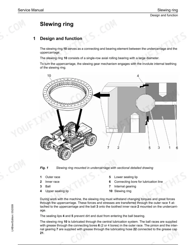
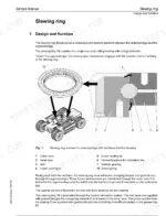
| Group 10 - Swing Ring | 2011-2020 | Slewing Ring, Tilting Play, Factory Play, Maximum Tooth Backlash, Weight of Uppercarriage with and Without Attachment |
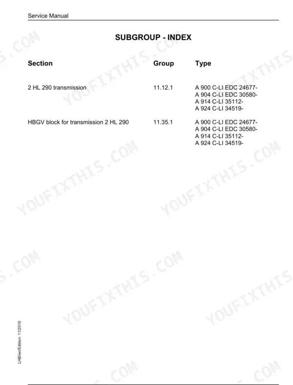
| Group 11 - Two Speed Gear Box | 2021-2056 | 2 HL 290 Transmission, HBGV Block for Transmission, Shifting Piston, Shift Lock Positions, Lubricating Oil Pump, Leakage Check Valve |
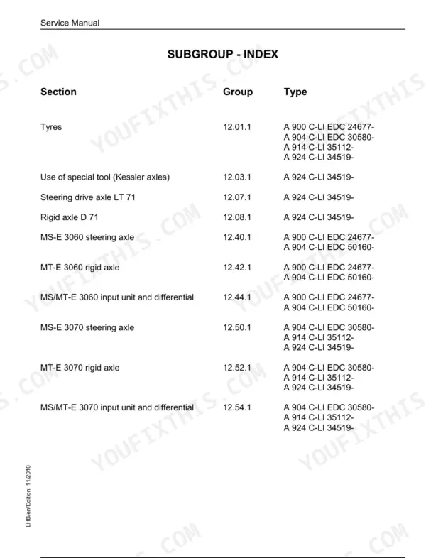
| Group 12 - Axles and Gear Box | 2057-2166 | Axle Housing, Ms-E 3060 Steering Axle, Design of Output Unit, Checking Tyre Pressure, Roller Bearings and Shaft Seals, Technical Data |
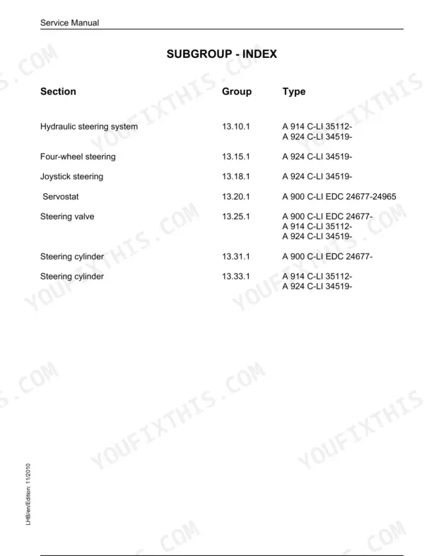
| Group 13 - Steering | 2167-2224 | Hydraulic Steering System, Steering Valve, Steering Cylinder, Servostat, Joystick Steering, Four-Wheel Steering, Replacement of Steering Cylinder Sealing Elements |
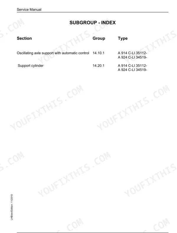
| Group 14 - Oscillating Axle Stabilizer | 2225-2242 | Oscillating Axle Support with Automatic Control, Support Cylinder, Stop Valve, Sectional Drawing, Replacing Support Cylinder Sealing Elements |
| Group 15 - Brake System | 2243-2270 | Hydraulic Brake System, Compact Brake Block, Operating Pressures of the Brake System, Inspection and Adjustment of Brake Settings, Pressure Switch and Brake Light, Brake Piston |
| Group 16 - Special Attachments and Accessory Kits | 2271-3008 | Likufix Hydraulic Coupling System, Hydraulic Operator's Cab Elevation System, Tool Management, Electronic Stick Cylinder Shut-Down, AHS 11 and AHS 12 Proportional Control, Plug Connections |
| Group 17 - Cab Heater and Air Conditioning System | 3009-3098 | Heating and Air-Conditioning System, Auxiliary Heater, Description and Operation of Test Menu, Fault Diagnosis, Inspection and Repair Instructions |
| Group 18 - Undercarriage, Uppercarriage and Attachments | 3099-3168 | Fully Automatic Central Lubricating System, Central Lubrication Pump, Sx-E Progressive Distributor, Mx-F Progressive Distributor, Semi-Automatic Central Lubrication System, Fixture of Operator's Cab Elevation System |
Quick Reference Specifications
| Specification | Value | Page |
|---|---|---|
| Engine (A 900 C / A 904 C) | Liebherr D 934 SA6 diesel | p. 725 |
| Engine (A 914 C / A 924 C) | Liebherr D 934 S/L A6 diesel | p. 729 |
| Lubricating oil, standard oil pan | max. 20.5 l / min. 13.5 l | p. 725 |
| Oil change with filter replacement | approx. 29 l | p. 725 |
| Cooling liquid including coolant | 30 l | p. 725 |
| Engine mounting bolts | pre-tighten with torque 60 Nm, then final tightening angle | p. 726 |
| Primary pressure, safety valve (A 900 C LI, Type 1002, protocol V4.3) | 400 +20 bar at measuring point 41 | p. 251 |
| Control valve block, pressure-relief valves | 120 Nm | p. 1136 |
| Wheel nut torque (A 900 C / A 904 C) | 460 Nm | p. 2060 |
| Main pump | Variable-displacement pump DPVO 165 | p. 944 |
Liebherr A 900 C, A 904 C, A 914 C, A 924 C Litronic EDC Common Problems This Manual Covers
Travel drive feels weak, noisy, or the machine drags in one speed range
Start with the DMVA regulating motor section in Group 7, then work through the 2 HL 290 transmission in Group 11: the shifting piston, shift lock positions and leakage check valve procedures there catch most cases where one range drags or the drive hunts between speeds.
Manual Section: Group 7 - Hydraulic Components; Group 11 - Two Speed Gear Box p. 931Hydraulic functions slow or weak, pump whines under load or during swing
Do not swap the DPVO 165 pump on a hunch. Group 6 lays out the LSC system with full circuit diagrams, and Group 3 gives the measuring points and value measured record sheets, so you can test against your specific model's adjustment protocol before spending pump money.
Manual Section: Group 6 - Hydraulic System; Group 3 - Technical Data and Maintenance Guidelines p. 835Fault code on the display, RPM will not change, machine falls into reduced function
Group 8 walks you through the arrangement of components, the right console, and the BBT/DISP2 service level with machine-specific settings, then the kit wiring diagrams let you trace the actual input circuit. Group 4 covers the Datalogger for reading what the electronics recorded.
Manual Section: Group 8 - Electrical System; Group 4 - Engine (Datalogger) p. 1253Swing whines, hesitates, or the uppercarriage will not hold position on a slope
Group 9 covers the slewing gear mechanism plus positioning and repair of the slewing brake, which is the usual culprit when the house creeps. Then use Group 10 to measure tilting play against factory play and maximum tooth backlash before condemning the slewing ring itself.
Manual Section: Group 9 - Swing Gear; Group 10 - Swing Ring p. 1981Frequently Asked Questions
Will this manual get me into the Litronic EDC diagnostics to deal with fault codes?
Yes, this is the Litronic EDC generation, so electronic diagnosis is real work here. Group 8 documents the BBT/DISP2 display, the service level and the machine-specific settings, and Group 4 covers the Datalogger (software version 2.3.09) including its settings menu and the software update procedure. If your machine has dropped into reduced function or a control input like the throttle stops responding, this is where you get past the operator screens and onto the service side. p. 1253
Does it have the torque specs people actually search for?
The common ones are in here and they are specific. Wheel nuts: 460 Nm on both the A 900 C and the A 904 C. Engine mounting bolts are a two-stage job: pre-tighten to 60 Nm, then a final tightening angle, so do not pull them to a single number. The LSC control valve block page alone lists check valve 10 Nm, valve seat 15 Nm, pressure balance 25 Nm, pressure cut-off valve 25 Nm, shift valve 80 Nm and pressure-relief valves 120 Nm. p. 1136
Are hydraulic pressure settings included, and do they match my exact model?
Yes, and this part matters: the book carries a separate adjustment protocol for each model and type, so a pressure from one machine does not transfer to another. Example: the A 900 C LI Type 1002 protocol (V4.3) sets the primary safety valve at 400 +20 bar at measuring point 41, and lists slewing gear primary pressure at 200 - 240 bar (minus 10 tolerance) at points 137/138, preset by the BST with no adjustment necessary. Find your model's protocol and use those numbers, not your neighbour's. p. 251
Which engines and fluid capacities does it cover?
The A 900 C and A 904 C run the Liebherr D 934 SA6 diesel; the A 914 C and A 924 C run the D 934 S/L A6. Capacities are printed where you need them: standard oil pan max. 20.5 l / min. 13.5 l, about 29 l for an oil change with filter replacement, 30 l of cooling liquid, and a 50/50 antifreeze mix good to -37 C. Group 1 adds the approved lubricants and oil supplier tables. p. 725
Are the wiring and hydraulic diagrams complete enough to actually trace a circuit?
This is where the book earns its price. You get 21 A3 fold-out hydraulic circuit sheets covering the different equipment types, plus full colour wiring diagrams organised by electrical kit, down to items like the lift frame kit. Group 16 also documents the LIKUFIX coupler, cab elevation, electronic stick cylinder shut-down and AHS 11/12 proportional controls with their plug connections, which aftermarket wiring guides never touch. p. 1790


Reviews
There are no reviews yet.