
Fits the Liebherr A 309 - R 317 Litronic range: A 309, A 311, A 312, R 313, A 314, A 316 and R 317, book edition 01/2008. Serials start at A 309 LI 20221, A 311 LI 20222, A 312 LI 12363, R 313 LI 27752, A 314/A 316 LI 2001 and R 317 LI 18161.
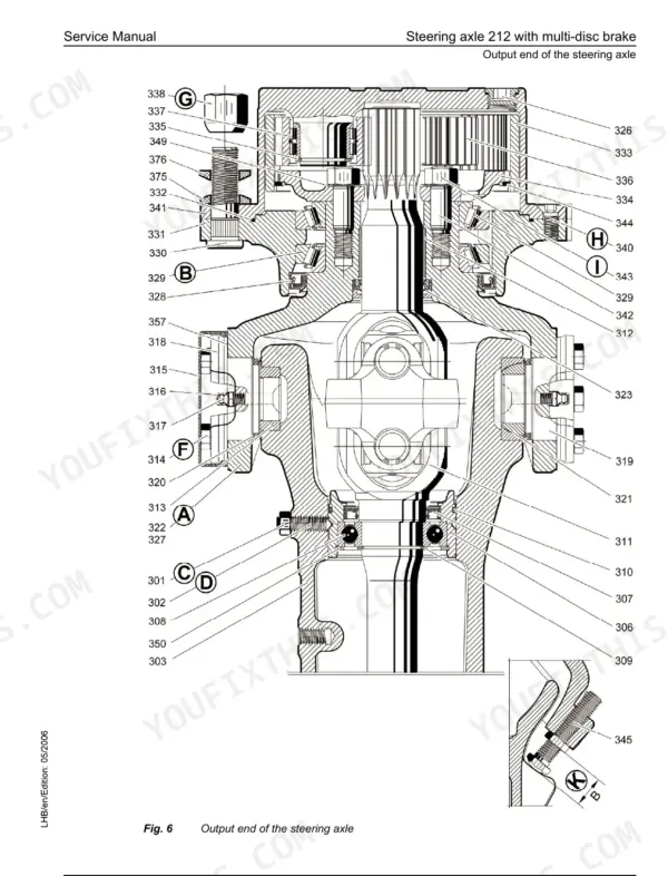
When one of these sits dead on site, the crew stands with it and the day is gone. The book runs from Deutz engine data, pump distribution gear and hydraulic adjustment protocols through BST control and circuit diagrams. It carries on through slewing gear and ring, transmission, axles, steering, brakes, cab and tanks.
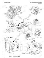
The electrical item location lists and component descriptions let you name the exact solenoid or sensor before you ring the dealer. That way the right part turns up on the first order.
What's Inside This Liebherr A 309 - R 317 Litronic Manual
| System | Pages | Key Topics |
|---|---|---|
| General and Safety | 1-76 | Modification of Series by Serial Number, Safety Instructions, WN 4037 Tightening Torques, Cylinder Assembly Instructions, Fuels and Lubricant Lists |
| Tools | 77-122 | Special Tools and Service Equipment |
| Technical Data and Maintenance Schedules | 123-170 | Technical Data Sheet per Model A 309 to R 317, Inspection and Maintenance Schedules |
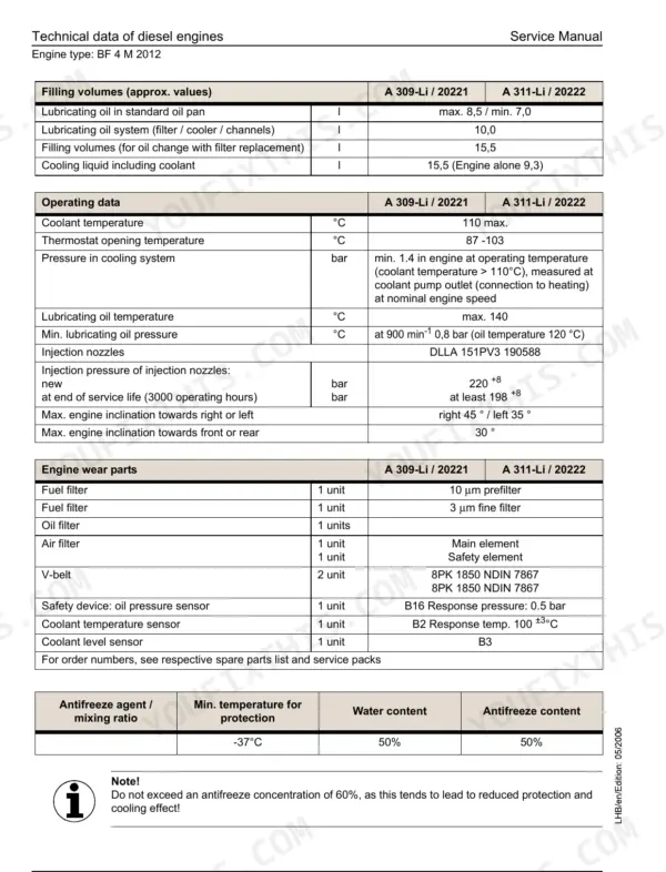
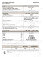
| Drive Motor (Deutz Engines) | 171-186 | Engine Technical Data: BF 4 M 2012, BF 4 M 2012 C, BF 4 M 1013 E, BF 4 M 1013 EC |
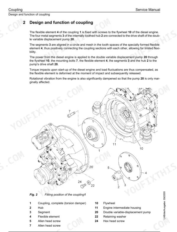
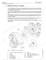
| Coupling and Pump Distribution Gear | 187-198 | Engine-To-Pump Coupling and Pump Distribution Gearbox, Design and Function of Coupling, Installation and Dismantling of the Coupling |
| Hydraulic System | 199-506 | Adjustment Protocols and Guidelines per Model, LSC System, Pump Regulation, Pressure Relief Settings, Hydraulic Diagrams |
| Hydraulic Components | 507-854 | Pumps, Control Valve Blocks, Cylinders, Rotary Connection and Valves |
| Electrical Components and Layouts | 855-964 | Electrical Component Description and Arrangement, Sensors / Transducers, Overview of Control Console, Battery and Battery Main Switch, Solenoid Valves |
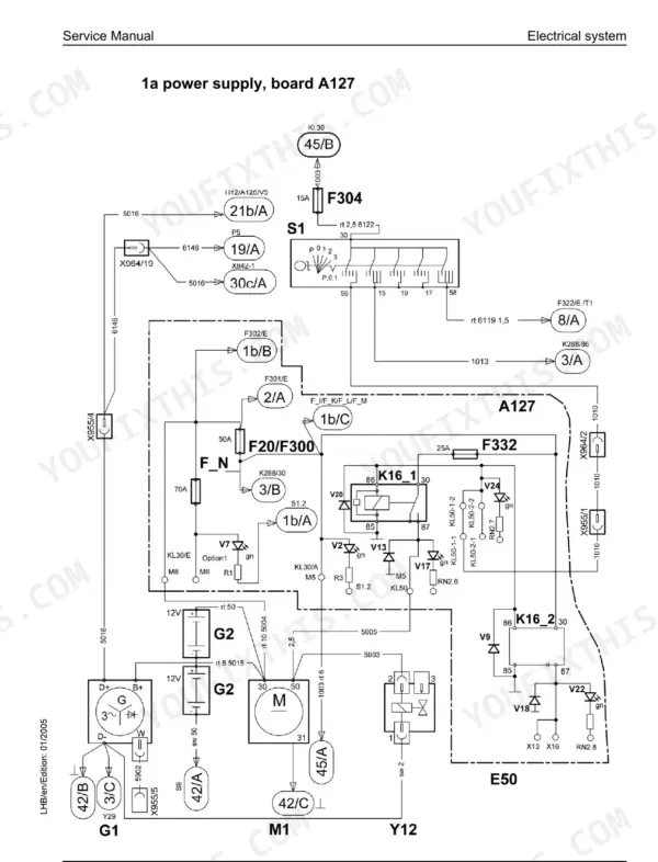
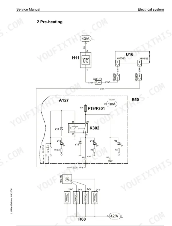
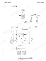
| Electrical Circuit Diagrams | 965-1300 | Electrical System Circuit Sheets by Model and Serial Range, Pre-Heating, Travel Direction Switch, Automatic Oscillating Axle Locking Device, Optional Overload Warning System |
| Component Locations and Electric Kits | 1301-1548 | Electrical Item Location List, Accessory Kit Diagrams |
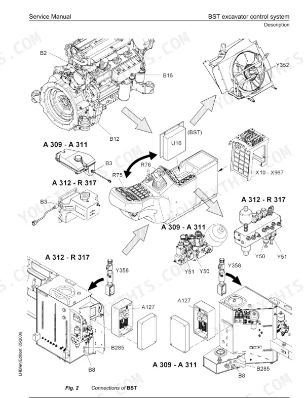
| BST Excavator Control and Slip Ring | 1549-1652 | BST Control System, Fault Codes, Service Interface X838-1, Slip Ring Rotary Connection |
| Slewing Gear Mechanism | 1653-1682 | Slewing Gear and Slewing Drive |
| Slewing Ring | 1683-1692 | Slewing Ring Tilting Play, Mounting Bolt Torques, Replacement |
| Transmission | 1693-1838 | 2 HL Transmissions, Gearbox Components |
| Axles | 1839-2136 | Front and Rear Axles, Planetary Hubs |
| Steering | 2137-2220 | Steering System and 4-Wheel Steering |
| Oscillating Axle Support | 2221-2244 | Oscillating Axle Lock |
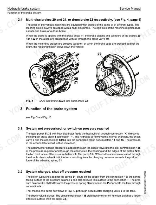
| Brake System | 2245-2270 | Compact Brake Block and Service Brakes |
| Special Equipment and Accessory Kits | 2271-2594 | Quick Change Adapter, AHS Kits, Dozer Blade, Generator Drive |
| Operator's Cab, Heating and Air-Conditioning | 2595-2624 | Cab, Heater and Air-Conditioning System |
| Undercarriage, Uppercarriage and Attachments | 2625-2630 | Undercarriage, Uppercarriage and Attachment |
| Tank Arrangement | 2631-2649 | Fuel and Hydraulic Tank Arrangement |
Quick Reference Specifications
| Specification | Value | Page |
|---|---|---|
| All Models | ||
| Engine model | BF 4 M 2012 (A 309 Litronic, A 311 Litronic) / BF 4 M 2012 C (R 313 Litronic) / BF 4 M 1013 E (A 312 Litronic) / BF 4 M 1013 EC (A 314 Litronic, A 316 Litronic, R 317 Litronic) | p. 173 |
| Power (DIN / ISO 9249) | 63 kW (86 PS) (A 309 Litronic) / 67 kW (91 PS) (A 311 Litronic) / 73 kW (99 PS) (R 313 Litronic) / 74 kW (100.7 HP) (A 312 Litronic) | p. 173 |
| Slewing ring mounting bolts | M 16, 10.9, 280 Nm (A 309, A 311, A 312) / M 20, 10.9, 560 Nm (R 313, A 314, A 316, R 317) | p. 1686 |
| all models | ||
| Slewing ring max. tilting play | 1.5 mm | p. 1686 |
| A 309 Litronic from 20221 | ||
| Begin of pump regulation, Pump P1 | 50 ±2 bar | p. 204 |
| A 314 Litronic | ||
| Power (DIN / ISO 9249) | 82 kW (109 PS) | p. 183 |
| A 316 Litronic, R 317 Litronic | ||
| Power (DIN / ISO 9249) | 86 kW (115 PS) | p. 183 |
Liebherr A 309 - R 317 Litronic Common Problems This Manual Covers
Hydraulics dead or cutting in and out after start-up
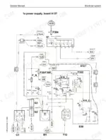
Open the Electrical Circuit Diagrams sheet for your serial range and trace the 24V feed to each solenoid valve. The Component Locations list shows where each item sits on the machine. Meter the coil and check the connector before you condemn the control valve block. The valve block itself is covered under Hydraulic Components.
Manual Section: Electrical Circuit Diagrams; Component Locations and Electric Kits; Hydraulic Components p. 1140Slow or weak hydraulics under load
Work through the Hydraulic System adjustment protocol for your model, in order. It covers the LSC system, pump regulation and pressure relief settings. On an A 309 from 20221, pump regulation on P1 should begin at 50 ±2 bar. Set pressures in the order the book gives, not one at a time as you go.
Manual Section: Hydraulic System p. 204Sluggish swing or play in the upper structure
Measure tilting play at the slewing ring first. The Slewing Ring chapter gives 1.5 mm as the maximum on all models. If the ring is within that limit, move on to Slewing Gear Mechanism for the slewing drive. Retorque the mounting bolts to the value for your model: 280 Nm on M 16 or 560 Nm on M 20.
Manual Section: Slewing Ring; Slewing Gear Mechanism p. 1686Loss of travel drive or dragging on wheeled A models
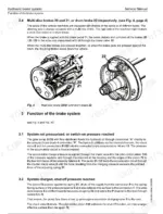
On the wheeled A machines, start in the Transmission chapter for the 2 HL gearbox, then go to Axles for the planetary hubs. Check the Brake System chapter as well. A compact brake block that will not release can feel just like a dead final drive. Crawler R models are covered under Undercarriage.
Manual Section: Transmission; Axles; Brake System p. 1693Frequently Asked Questions
My R 317 starts, but nothing moves. No travel and no hydraulics at all. Where do I begin?
Before you pull any hoses, work out whether the fault is in supply, pilot or electrics. The Hydraulic System chapter gives the adjustment protocols and hydraulic diagrams for your model, so you can check pressures against spec. If pressure is there but nothing responds, go to the BST section and the circuit sheets for your serial range. A dead 24V solenoid or a lost interlock feed can look just like a failed pump. p. 204
How do I read the BST fault codes, and can I clear them from the cab?
The codes are three digits, such as 007, 022 or 501. You read them with a laptop plugged into service interface X838-1. Indicator light H301 shows off, flashing or continuous, and the BST section explains what each state means. The book gives no procedure for clearing or resetting codes from the cab, so plan on bringing the laptop. p. 1561
Will this book match my machine's serial number?
It covers seven models from these serials: A 309 LI 20221, A 311 LI 20222, A 312 LI 12363, R 313 LI 27752, A 314/A 316 LI 2001 and R 317 LI 18161. The General section lists series modifications by serial number. Check your plate against that list before you trust a setting. p. 123
What are the slewing ring bolt torques and the wear limit?
The A 309, A 311 and A 312 use M 16 bolts, grade 10.9, torqued to 280 Nm. The R 313, A 314, A 316 and R 317 use M 20, grade 10.9, at 560 Nm. Maximum tilting play is 1.5 mm on every model. If you measure more than that, the Slewing Ring chapter covers replacement. p. 1686
Which Deutz engine is in my machine?
The A 309 and A 311 have the BF 4 M 2012, rated 63 kW (86 PS) and 67 kW (91 PS). The R 313 has the BF 4 M 2012 C at 73 kW (99 PS). The A 312 has the BF 4 M 1013 E at 74 kW (100.7 HP). The A 314, A 316 and R 317 use the BF 4 M 1013 EC. p. 173


Reviews
There are no reviews yet.