
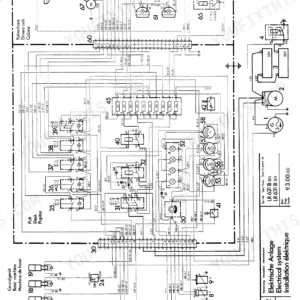
Printed by Liebherr under ID 10359401, this 790-page Liebherr R 924 service manual PDF is the factory workshop book for the R 924 Compact hydraulic excavator and material handler. Load sensing control, the hydraulic layout and the adjustment guidelines take up a large share of the book, backed by hydraulic schematics and teardown coverage of the DPVP 108 double variable-displacement pump, the hydraulic motors and the cylinders. Wiring diagrams sit with an electrical section on the S2 control unit and monitoring display, and your undercarriage work is covered as well, from track component wear and removal to swing gear, travel gear and central lubrication. Check leak oil against the 8 l/min maximum at 300 bar, and torque the M12x35 grade 10.9 bolts to 110 Nm. Sometimes it's just you and the machine, with nobody to call. Bookmarks and a live text layer take you straight to the right page, and the R 924 goes back to work running.
What's Inside This Liebherr R 924 Compact Manual
| System | Pages | Key Topics |
|---|---|---|
| General Information | 1-73 | Safety Instructions |
| Tools | 74-131 | Special Tools for Maintenance and Repair, Special Tools for Liebherr Diesel Engines, Special Tools for the Hydraulic System, Special Tools for Electrical Connectors |
| Technical Data / Maintenance Guidelines | 132-149 | Technical Data, Control and Maintenance Chart |
| Engine | 150-155 | Engine Type D 924 TI-E |
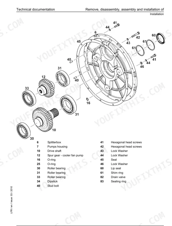
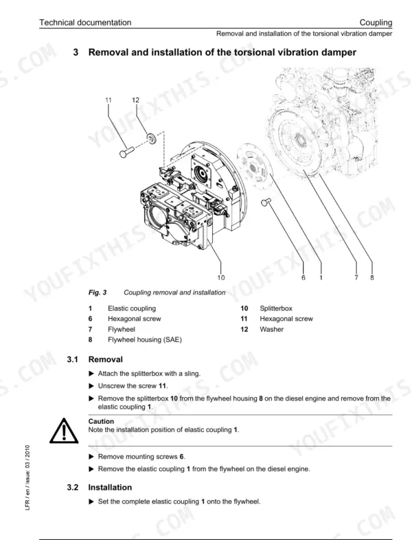
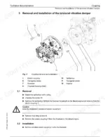
| Coupling / Splitterbox | 156-173 | Coupling, Splitterbox |
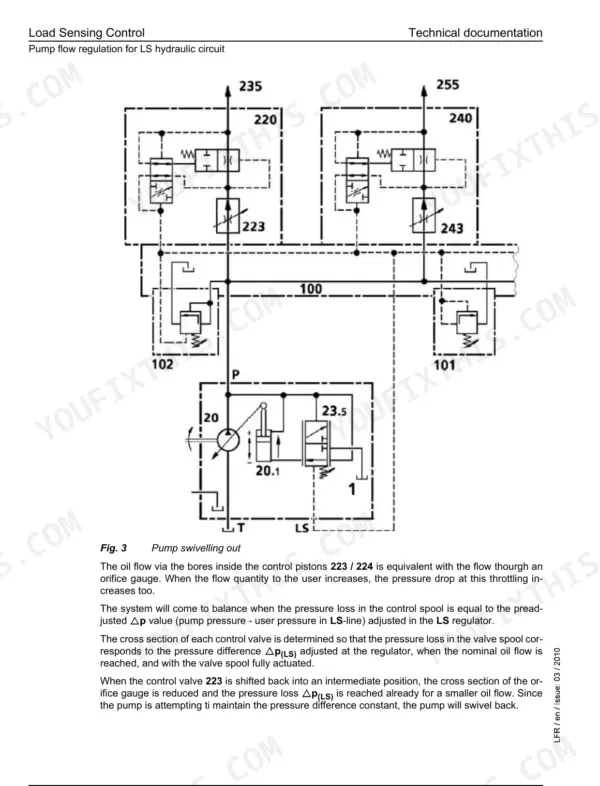
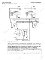
| Hydraulic System | 174-255 | Load Sensing Control, Layout of Hydraulic System, Adjustment Guidelines |
| Hydraulic Components | 256-381 | Double Variable-Displacement Pump DPVP 108, Hydraulic Fixed-Displacement Motor HMF 02, Hydraulic Variable Displacement Motor FMV, Hydraulic Cylinders |
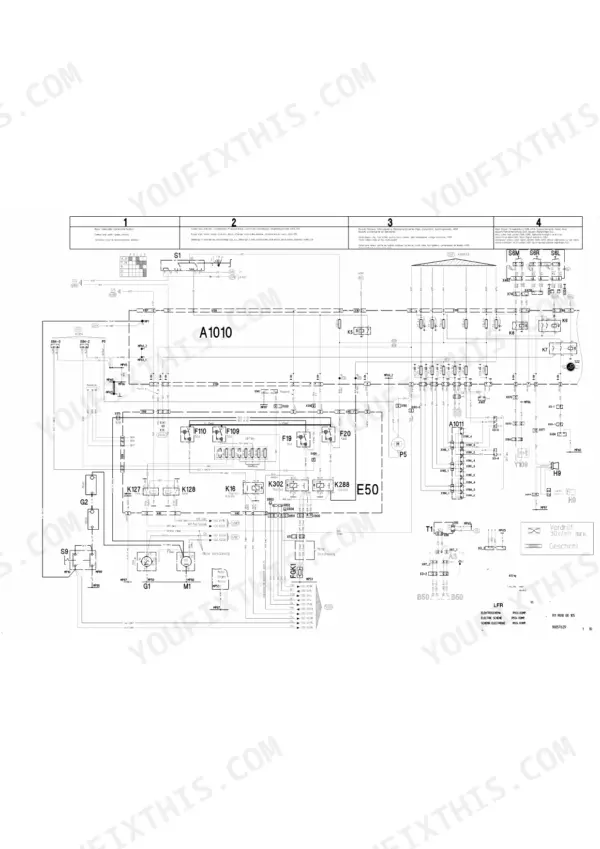
| Electrical System | 382-467 | Arrangement of Components, Monitoring Display, Control Unit S2 |
| Swing Gear | 468-489 | Swing Gear Transmission GS3000-2, Swing Gear Brake |
| Swing Ring | 490-501 | Swing Ring Function |
| Travel Gear | 502-521 | Travel Gear FAT |
| Track Components | 522-569 | Wear on Track Components, Removal and Installation of Track Components |
| Options | 570-605 | Pipe Fracture Safety Valve, Hydraulic Installation Kit AHS 11 |
| Cab / Heater / Air Conditioning System | 606-669 | Auxiliary Heating D5WS, Heating and Air-Conditioning System |
| Central Lubrication | 670-790 | Centralized Lubrication System, Lubrication Pump, Progressive Distributor SX-E, Progressive Distributor MX-F |
Quick Reference Specifications
| Specification | Value | Page |
|---|---|---|
| Max. torque | 760 N.m (at 1500 rpm) | p. 134 |
| 2x M12x35-912-10.9 | 110 Nm | p. 283 |
| Boom cylinder Ø piston / rod | (2x) 130 / 90 mm (Type 1055), (2x) 140 / 85 mm (Type 1056 / 1083 Tunnel) | p. 135 |
| Max. leak oil at (300 bar) | 8 l/min | p. 284 |
| Lowering speed of the attachment | ~4 sec. | p. 142 |
| Emergency operation speed | approx. 1700 rpm | p. 199 |
| Fan speed with air-conditioning system activated | approx. 1000 rpm | p. 199 |
| Valve nominal width (220 Hoist cylinder) | 25 (1") mm | p. 346 |
| Valve nominal width (240 Stick cylinder) | 25 (1") mm | p. 346 |
| Axial play max at delivery | 0,6 mm | p. 493 |
| Axial play maximum | 1,8 mm | p. 493 |
| Dry weight approx. | 180 kg | p. 506 |
Liebherr R 924 Compact Common Problems This Manual Covers
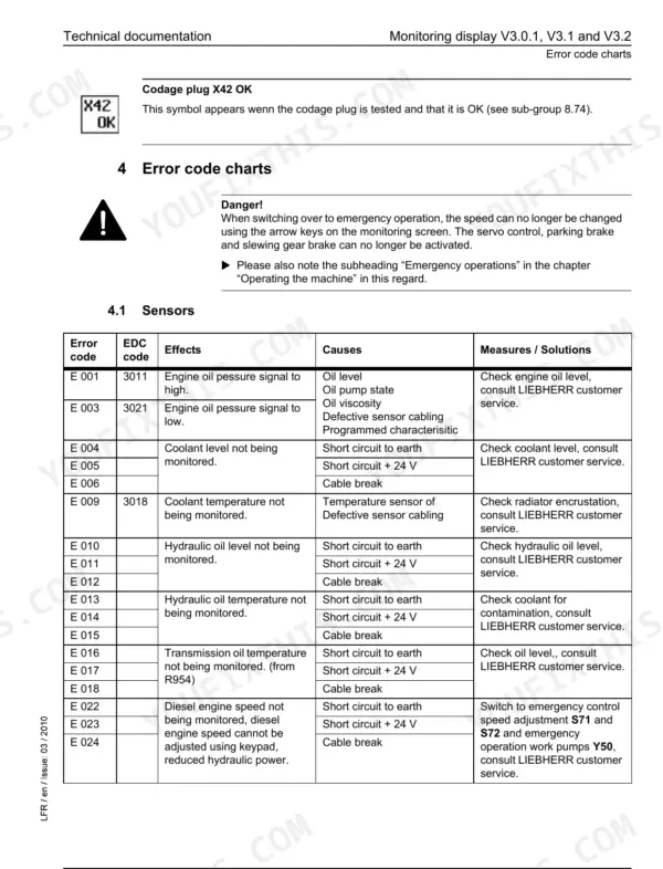
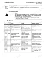
Liebherr R 924 monitoring display showing error codes for sensors, regulating circuit, keypad or coding faults
Check the active code on the monitoring display and match it against the error code tables, where faults are grouped as sensor, regulating circuit, keypad, display and coding errors. Test the flagged sensor or circuit before you condemn the display itself, and sort out any coding error before chasing other symptoms.
Manual Section: Monitoring Display Error CodesBoom or stick hydraulic cylinder with worn cushioning pin and seals leaking oil
Remove and disassemble the cylinder following the Hydraulic Cylinder Repair procedure, then do the sealing work and replace the cushioning pin if it is worn. Verify the bore before ordering parts: boom cylinders are 130 / 90 mm piston and rod on Type 1055, or 140 / 85 mm on Type 1056 and 1083 Tunnel, per page 135.
Manual Section: Hydraulic Cylinder RepairHydraulic control valve block leak oil from the control pistons measuring higher than expected
Measure leak oil at the control pistons following the Hydraulic Control Valve Block Leak Oil Inspection before you pull the block. Confirm which section you are on: hoist and stick sections are 25 mm (1") nominal width with 32 mm piston rod diameter, while bucket and travel sections are 18 mm (3/4") with 25 mm, per page 346.
Manual Section: Hydraulic Control Valve Block Leak Oil InspectionSwing ring axial play and backlash measuring beyond the factory wear limits
Measure axial play on the swing ring and compare it against page 493: 0,6 mm maximum at delivery and 1,8 mm maximum in service. Check backlash against the 1,4 mm maximum. If the ring comes off or the mounting screws are disturbed, torque them to 560 Nm on reassembly before returning the machine to work.
Manual Section: Swing Ring p. 493Cab air-conditioning system starts but shuts down, gives no cooling effect, or makes intense noises
Match the operator's complaint (no start, starts then shuts down, no cooling effect, intense noises) to its branch in the Air-Conditioning System Faults chart and work through it in order. Verify fan speed reaches approx. 1000 rpm with the air-conditioning system activated, as listed on page 199, before condemning anything in the cab.
Manual Section: Air-Conditioning System FaultsCentral lubrication system leaking grease, pumping too much grease, or pump out of order
Inspect the system against the Central Lubrication System Breakdowns table, working the branch that matches the complaint: grease leak, too much grease, pump out of order, or no grease delivery. Check the lubrication pump and the SX-E or MX-F progressive distributor, and trace the pump electrics on the wiring diagram.
Manual Section: Central Lubrication System BreakdownsFrequently Asked Questions
How do I reset the Liebherr R 924 Compact fault code?
To delete error messages in the menu i Exxx, plug the green service plug into connector X31 on the printed circuit board A 1001 (ESP01). This action should delete the error messages in the menu. For further details on deleting cable errors, refer to the service handbook section on the monitoring display. p. 220
What is the Liebherr R 924 Compact error code list?
The manual provides detailed error code charts for sensors (E001-E024), the regulating circuit (E027-E080), the keypad (E302-E307), the display (E308, E601), coding errors (E309-E322), and other errors (E442-E458). These charts, found on pages 412-415, list the error code, its effect, the potential cause, and the recommended measures or solutions. p. 412
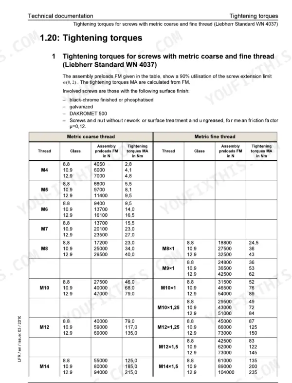
What are the torque specifications for the Liebherr R 924 Compact?
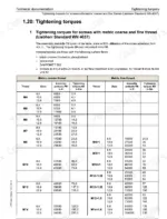
Tightening torques for screws with metric coarse and fine threads are provided in tables on pages 26 and 27. For example, an M4 screw with class 8.8 has a tightening torque of 2.8 Nm, while an M36x1.5 screw with class 12.9 has a torque of 4470 Nm. p. 26
What is the oil quantity for the diesel engine on the R 924 Compact?
The oil quantity for the diesel engine (fulling quantity on oil change with filter) is 29 liters. p. 134
What is the procedure for bleeding the hydraulic cylinders?
For cylinders fitted with bleeder screws 2, use procedure 1: screw in gauge couplings 3, start the engine at low idle (800-900 RPM), and actuate the cylinder until oil free of air bubbles flows out. For cylinders without bleeder screws, use procedure 2: slowly extend and retract the cylinder to the stop 5 times. p. 300
Do I get instant access to this Liebherr R 924 Service Manual?
A single searchable PDF file of 790 pages, downloadable right after payment. Nothing ships, nothing waits in the mail.
Am I able to print pages from this Liebherr R 924 manual?
Yes. Print individual pages or full chapters for your own shop use, on letter or A4 paper.

Reviews
There are no reviews yet.