


Part of the Yanmar Parts Manuals.
Need the factory exploded views for your crawler backhoe? This 15-page Yanmar B37V-1, 3TNE88-B1A Parts Catalog PDF (OEM #000Y00S3700) breaks down every assembly on the machine. You get high-quality diagrams showing the exact relationship between track rollers, crawler frames, and drive sprockets. Open to the hydraulic section to see a complete breakdown of the turning motor cartridge assembly and multi-section control valve. Verify the exact component layout for the T1-port on the control valve assembly before you call the dealer, and confirm the arrangement of the gear pump coupling. Ordering the wrong part costs you days of downtime. Bookmarked by system so you can jump straight to the right diagram, find your number, and get your parts order in today.
What's Inside This Yanmar B37V-1, 3TNE88-B1A Parts Manual
| System | Pages | Key Topics |
|---|---|---|
| Preface | 1-2 | This Parts Catalog Is the 1st Edition of Yanmar Crawler Backhoe B37V - 1 for Model Name, Important Notes on Parts Catalog Usage |
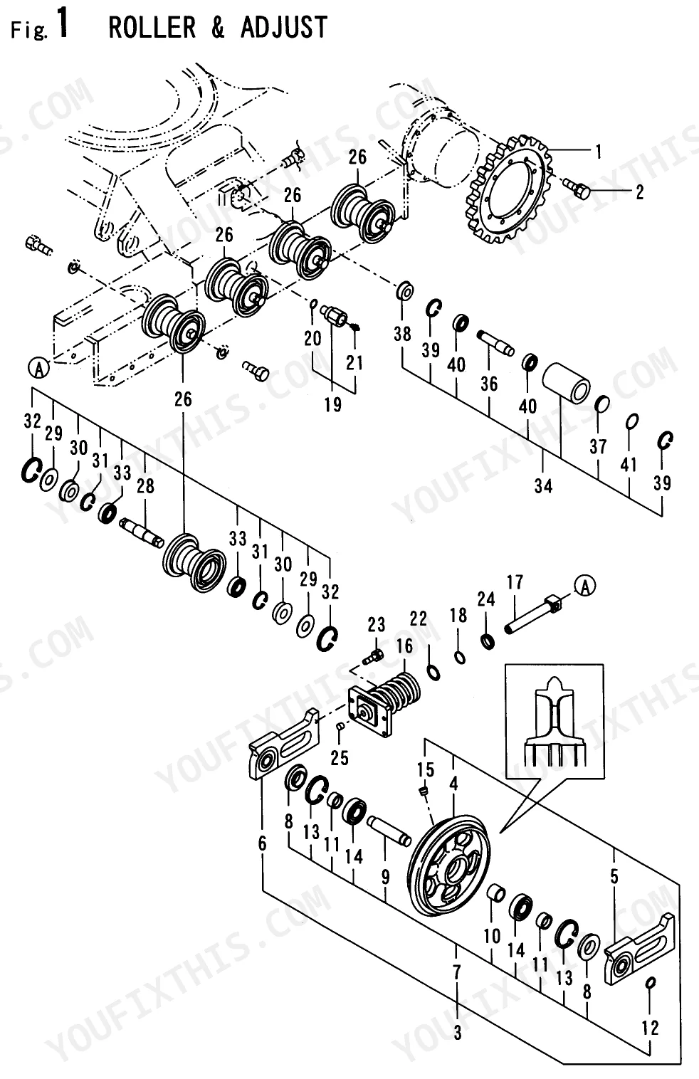
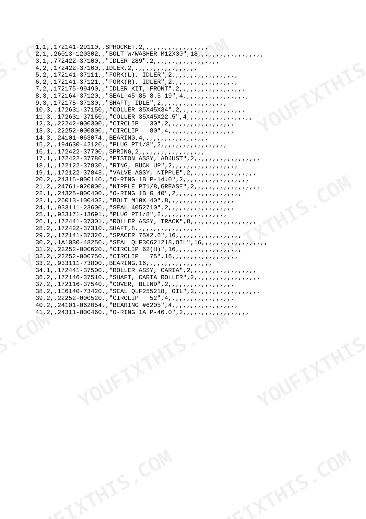
| Roller & Adjust | 3-4 | Sprocket, Idler Assembly, Track Roller Assembly, Adjuster Assembly, Carrier Roller Assembly |
| Crawler | 5-6 | Track, Track Frame Assembly, Drive Sprocket, Front Idler Wheel |
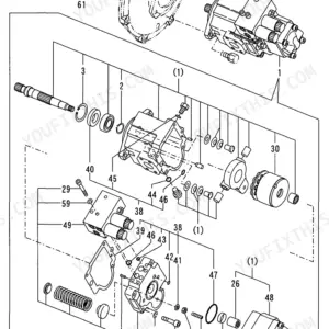
| Hyd. Oil Pump & Joint | 7-8 | Pump Assembly, Coupling, Valve Block Assembly, Gear Pump |
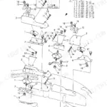
| Turning Motor | 9-10 | Motor Component, Valve Shockless, Cartridge Assembly, Gear |
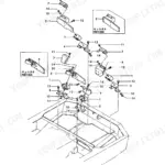
| Control Valve | 11-15 | Assembly, T1-Port, Bucket Section, P1 P2-Port, Boom Section, Drive Section, Swing Section |
Yanmar B37V-1, 3TNE88-B1A Common Problems This Manual Covers
Yanmar B37V-1 crawler backhoe hydraulic gear pump is leaking and needs replacement part numbers
Inspect the hydraulic parts diagram on page 7. Locate the gear pump and coupling components in the exploded view. Cross-reference the item numbers with the parts list to find the exact replacement part numbers for your machine. Always order 1 set of new O-rings.
Manual Section: Hyd. Oil Pump & Joint p. 7Need the bucket section seal kit part numbers because the control valve is leaking hydraulic fluid
Review the control valve assembly diagrams starting on page 11. Find the bucket section and T1-Port components in the exploded view. Match the index numbers for the seals to the corresponding parts list. Verify compatibility with your serial number before ordering 1 complete replacement kit.
Manual Section: Control Valve p. 11Track adjuster assembly is completely seized up and need to order new idler wheel components
Examine the chassis parts diagram on page 3. Identify the front idler wheel, track roller assembly, and adjuster assembly in the detailed illustrations. Note the specific reference numbers for the carrier roller. Compare these numbers against the parts list to ensure you order the 2 exact replacements.
Manual Section: Roller & Adjust p. 3Swing function is weak and need correct cartridge assembly part numbers for the turning motor
Open the turning motor section on page 9. Locate the cartridge assembly, shockless valve, and gear components in the exploded diagram. Record the item numbers for the worn parts and look them up in the adjacent parts list. Always order 1 set of new gaskets for reassembly.
Manual Section: Turning Motor p. 9Frequently Asked Questions
What are the replacement specifications for seals and O-rings?
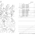
The manual provides replacement specifications for seals and O-rings through part numbers and dimensions. On page 2, part number 172164-37120 is listed as SEAL 45 85 8.5 19, indicating its dimensions. Part number 24315-000140 is described as O-RING 1B P-14.0. These details are essential for identifying and ordering the correct replacement parts. p. 2
Where are the gear pump and coupling component part numbers in this catalog?
The hydraulic oil pump section on page 7 covers the gear pump and coupling assembly in an exploded parts view. Locate the pump assembly, coupling, valve block assembly, and gear pump components in the diagram. Cross-reference item numbers with the adjacent parts list to find exact replacement part numbers. Always order a new O-ring set when replacing gear pump internals. p. 7
How do I find the turning motor cartridge assembly part numbers?
The turning motor section on page 9 provides an exploded parts view of the motor component, shockless valve, cartridge assembly, and gear. Identify the worn component in the diagram, note its item number, then look up the part number in the parts list on the same page. Order a new gasket set for reassembly when servicing the cartridge assembly. p. 9
What control valve and bucket section seal part numbers does the catalog cover?
Pages 11-15 cover the multi-section control valve including the bucket section, T1-port, boom section, drive section, P1/P2-port, and swing section. Each section seals and components are shown in exploded parts views with indexed item numbers. Match the index numbers for worn seals to the parts list entries to find the correct replacement part numbers. p. 11
How quickly can I access this Yanmar B37V-1, AMMANN YANMAR, 3TNE88-B1A manual?
Immediate download of the complete 15-page searchable Parts Catalog (0 MB). Access it on any device, from a laptop at your desk to a phone in the field.
Am I able to print pages from this Yanmar B37V-1, AMMANN YANMAR, 3TNE88-B1A?
Absolutely. No DRM or copy protection. Print the whole manual or just the pages you need. Any home or office printer works.
Reviews
There are no reviews yet.