


Part of the Yanmar Repair Manuals.
Need factory-level data for your Yanmar ViO50-6B compact excavator? This 702-page service manual (OEM #MMB44ENMA00101) covers both the ViO50-6B and Vi050-6B, from engine teardown to hydraulic system rebuild. Inside: full hydraulic circuit schematics tracing every line from pump to cylinder, plus seat mount, engine, and cabin wiring diagrams for a complete electrical picture. You also get page after page of torque tables, step-by-step pressure adjustment procedures for relief and cut-off valves, error codes with diagnostic detail, and a troubleshooting section that addresses real field problems including thermal shock of the travel motor and discontinuous arm movement. Set P1/P2 system relief to 24.5 MPa at 30 L/min, and torque your 1/4 G hydraulic hose fittings to 24.5–28.5 N·m before you button anything up. No more guessing at pressures with a chart from a different machine. Bookmarked by section and keyword-searchable; pull it up on your tablet right at the excavator and get back to work.
What's Inside This Yanmar ViO50-6B Manual
| System | Pages | Key Topics |
|---|---|---|
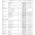
| 2-5 Specifications for Attachment | 15 | Dimensions, Oil Pressure Specifications, Hydraulic Pump Discharge Volume, Set Pressure of System Relief Valve, Set Pressure of Bucket Circuit Relief Valve |
| 2-6 Periodic Inspection and Servicing | 15 | General Inspections, Hydraulic Circuit, Greasing Points, Chassis, Electrical Equipment, Engine |
| 2-7 Fuel, Lube Oil and Grease Recommended | 16-33 | Thermal Engine Oil, Travel Gears Box Oil, Hydraulic Circuit Oil, Fuel Tank Diesel, Cooling System Fluid |
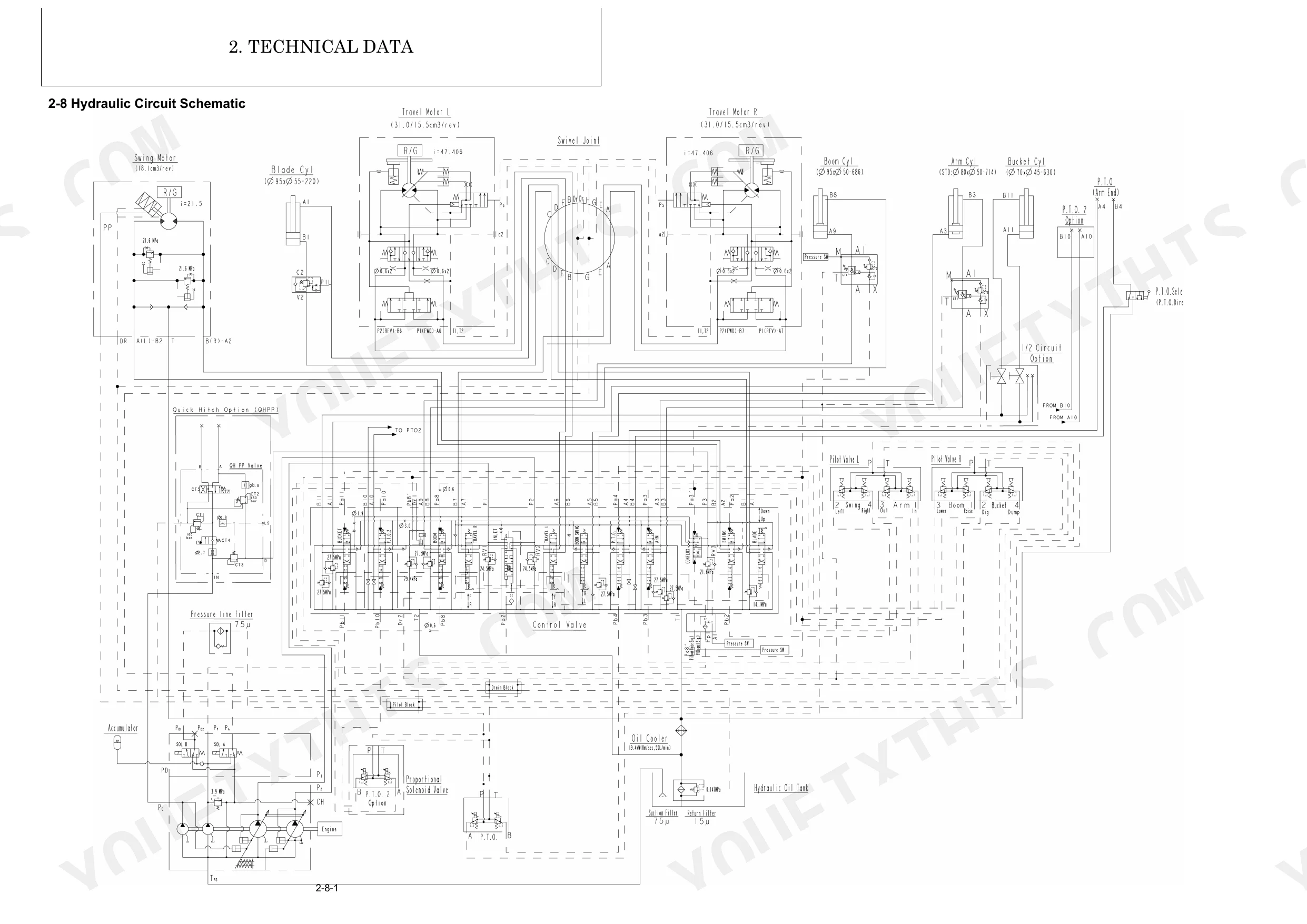
| 2-8 Hydraulic Circuit Schematic | 34 | Swing Motor, Travel Motor, Control Valve, Hydraulic Oil Tank, Hydraulic Cylinders, Swivel Joint |
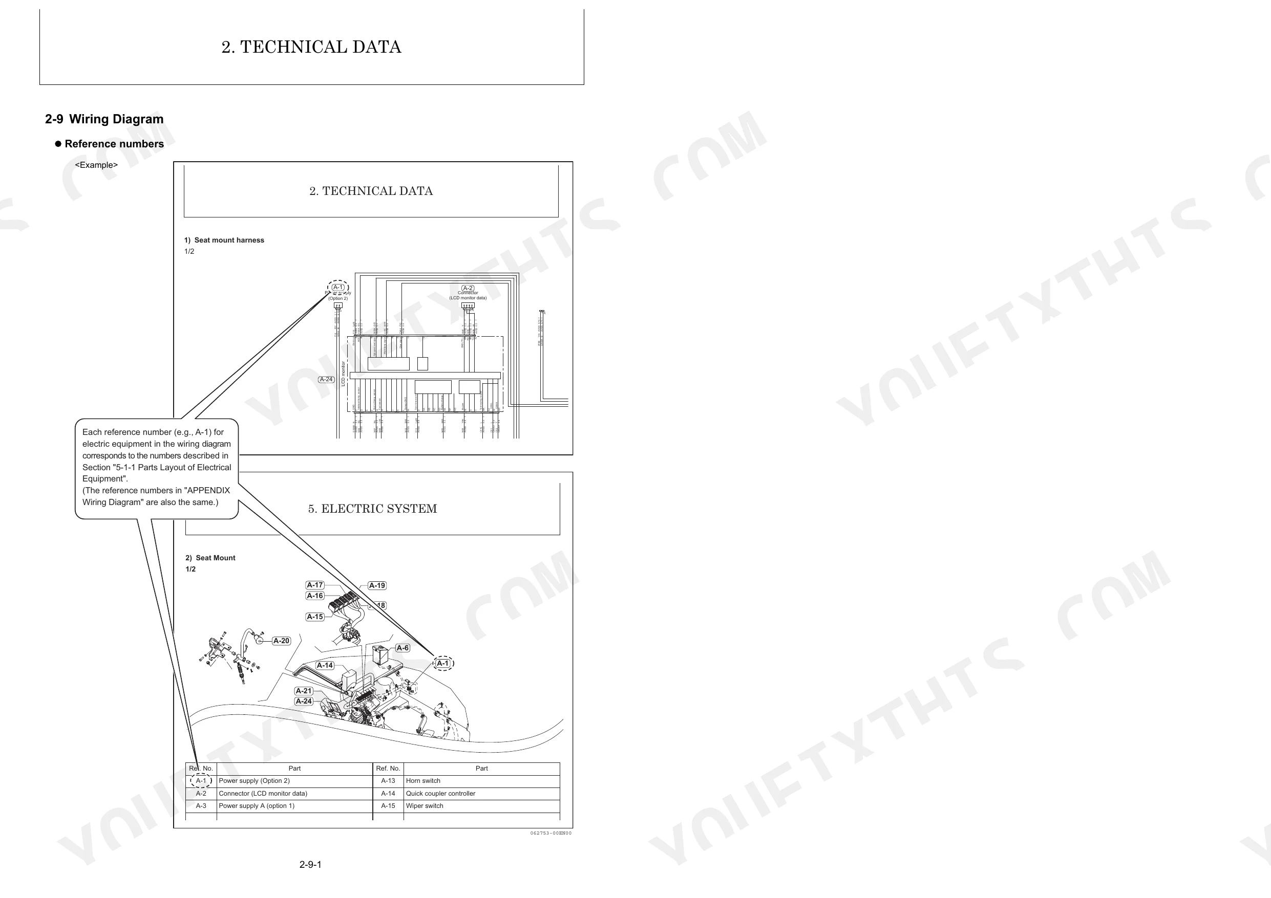
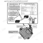
| 2-9 Wiring Diagram | 35-39 | Seat Mount Harness, Engine Harness, Cabin Wiring, Air Conditioner Wiring, Heater Wiring, Work Lamp Wiring |
| 3-8 Pressure Adjustment | 40-76 | Relief Valves, System Relief Valve, Circuit Relief Valve, Swing Brake Valve, Cut-Off Valve, Pressure Change |
| 4-1 Safety | 77-90 | Safety Statements, Safety Precautions, High Pressure Hazard, Scald Hazard, Explosion Hazard, Crush Hazard |
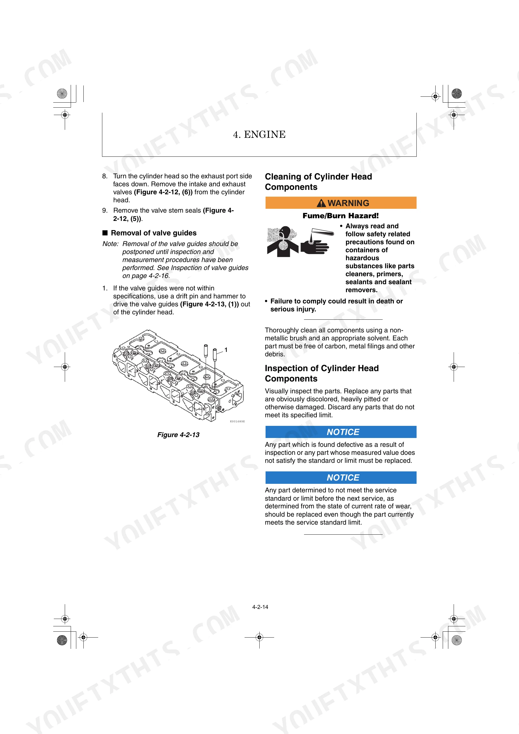
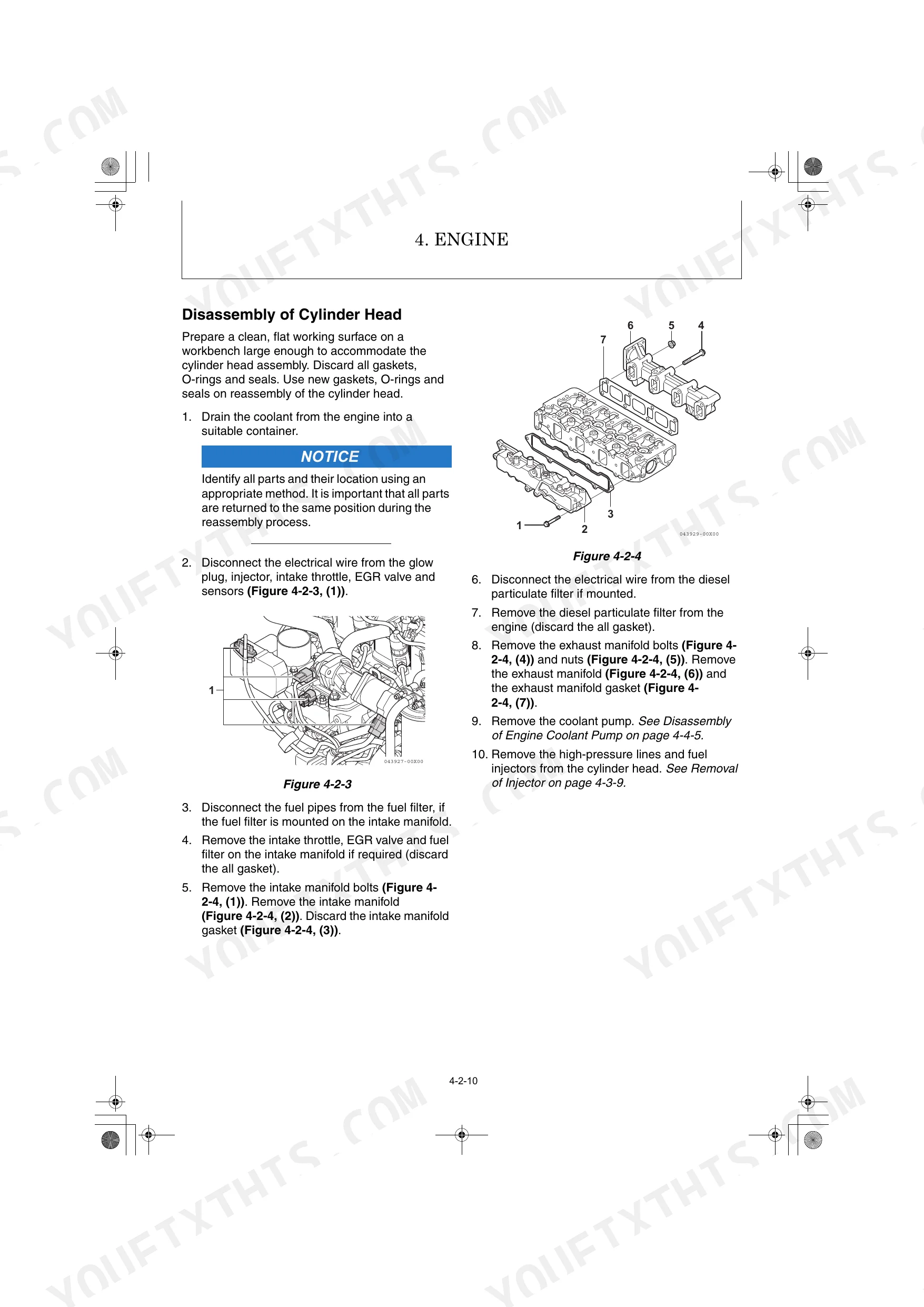
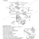
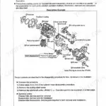
| 4-2 Engine | 91-148 | Special Service Tools, Measuring Instruments, Cylinder Head Components, Crankshaft Components, Camshaft Components, Timing Components |
| 4-3 Fuel System | 149-161 | System Structure, Fuel System Specifications, Fuel System Diagram, Fuel System Components, Common Rail, Injector |
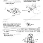
| 4-4 Cooling System | 162-169 | Cooling System Diagram, Engine Coolant Pump Components, Engine Coolant System Check, Temperature Switch, Thermostat, Radiator Cap |
| 4-5 Lubrication System | 170-175 | Lubrication System Diagram, Checking Engine Oil Pressure, Oil Pump Components, Disassembly of Oil Pump, Cleaning and Inspection, Reassembly of Oil Pump |
| 4-6 Starter Motor | 176-189 | Starter Motor Specifications, Starter Motor Troubleshooting, Starter Motor Components, Disassembly of Starter Motor, Cleaning and Inspection, Reassembly of Starter |
| 4-7 Alternator | 190-200 | - |
| 4-8 Electronic Control System | 201-237 | - |
| 4-9 Electric Wiring | 238 | - |
| 4-10 Failure Diagnosis | 239-242 | - |
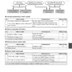
| 4-11 Troubleshooting | 243-250 | Non-Breakdowns (Natural Release of Bucket, Discontinuous Arm Movement, Drifting of Upperstructure on Quick Travel Operation, Thermal Shock of Travel Motor, Elongation of Boom Swing Cylinder on 68 Degrees Swing, Time Lag on Travel Speed Switching, Fluctuation in Oil Level of Hydraulic Oil Tank Due to Temperature Change) |
| 5-1 Electric Equipment of Machine | 251-287 | Parts Layout of Electrical Equipment, LCD Monitor and Alarm Systems |
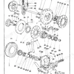
| 6-6 Swing Motor | 288 | Structure and Functions, Theory of Operation, Reduction Gear, Disassembly and Reassembly, Service Standards, Troubleshooting |
| 6-8 Proportional Solenoid Valve for P.T.O | 289-523 | Main Components, Specifications, Theory of Operation, Disassembly and Reassembly, Troubleshooting |
| 7-5 Hydraulic Equipment | 524 | Hydraulic Pump, Control Valve, Pilot Valves (L and R), Swing Motor, Swivel Joint, Hydraulic Cylinder |
| 7-7 Cabin | 524 | Removal and Reinstallation of Cabin, Disassembly and Reassembly of Cabin, Glass (Sash) Replacement, Installation of Interior Parts, Installation of Front Door |
| 7-8 Air Conditioner | 525-702 | Removal and Reinstallation of Air Conditioner, Removal of A/C (Heater) Unit, Removal of A/C Condenser, Removal of Compressor, Components, Air Conditioner Specifications |
Quick Reference Specifications
| Specification | Value | Page |
|---|---|---|
| Pressure oil gauge capacity | 49.0 MPa | p. 68 |
| System relief set pressure (P1, P2) | 24,5 MPa at 30 L/min | p. 68 |
| Crawler tension adjustment (Rubber Track) | H: 5 to 10 mm | p. 100 |
| Tightening torque for hydraulic hose (1/8 G (PF)) | 12 to 14 N·m | p. 102 |
| Tightening torque for hydraulic hose (1/4 G (PF)) | 24,5 to 28,5 N·m | p. 67 |
| Tightening torque for parallel pipe thread (1/8 G (PF)) | 24,5 to 28,5 N·m | p. 67 |
| Tightening torque for parallel pipe thread (1/4 G (PF)) | 38 to 42 N·m | p. 67 |
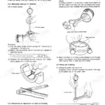
| Crankshaft oil seal replacement | Apply a continuous bead of ThreeBond Liquid Gasket No. 1207F, YANMAR Part No. 977770-1207F to the outside diameter of a new oil seal | p. 125 |
| Oil pickup tube O-ring replacement | Reinstall the oil pickup tube (Figure 4-2-102, (1)) using a new O-ring (Figure 4-2-102, (2)). | p. 139 |
| Fuel filter filtration area | 2000 cm² | p. 23 |
| Air filter replacement interval (dusty atmosphere) | every 250 h | p. 31 |
| LO filter filtration area | 1160 cm² | p. 23 |
Yanmar ViO50-6B Common Problems This Manual Covers
Yanmar ViO50-6B hydraulic oil leak around fittings or hoses after service or pipe replacement
Inspect connections for twisted hoses and verify fittings are fully seated before torquing. For 3/8 G (PF) hose fittings, torque to 45.5 to 49.5 N·m; 1/2 G (PF) parallel pipe threads go to 106 to 115 N·m (page 67). After assembly, cycle to maximum pressure 5 to 6 times (page 7), then re-inspect every joint and O-ring for seepage.
Manual Section: Pressure Adjustment p. 67Implement feels weak or cylinder drifts off position after hydraulic system work or seal replacement
Bleed air from all cylinders before returning to service. Slowly extend and retract each cylinder to within 50 to 100 mm of each stroke end 4 or 5 times, then fully cycle 3 or 4 times (page 14). Check boom drift: allowable rod retraction is 10 mm. Anything beyond that indicates internal seal failure, not trapped air.
Manual Section: Pressure Adjustment p. 14Engine temperature warning on the LCD monitor, coolant level low, or hoses soft and collapsing
Check coolant level before every startup; radiator capacity is 7.0 L (page 33). Squeeze hoses when cold: soft spots or collapse under pressure mean replacement is overdue. Retorque hose clips to 2.5 to 3.5 N·m (page 59). If temp still climbs with clean coolant, test the thermostat per the cooling system procedures starting at page 162.
Manual Section: Cooling System p. 162Rubber track sags or overtightens, sprocket teeth wearing unevenly, machine pulls to one side on travel
Park on flat ground and measure track sag at the midpoint between the sprocket and front idler. Rubber track deflection must be 5 to 10 mm (page 100). Add or release grease through the tension valve to adjust. Check tension again after the first work shift on new track, since rubber stretches faster than steel during initial break-in.
Manual Section: General Troubleshooting Quick Reference p. 100Engine stumbles under load, loses power, or stalls repeatedly with water visible in fuel filter bowl
Drain the fuel-water separator before wet-weather shifts: loosen the air vent screw on top 2 to 3 turns counterclockwise, let water drain, retighten (page 86). The filter element has 2,000 cm² filtration area (page 23); replace at the first sign of milky fuel, not just on schedule. Bleed the fuel system fully after any filter service.
Manual Section: Fuel System p. 86Frequently Asked Questions
What do error codes mean on a YANMAR ViO50-6B?
The manual provides a comprehensive 'Error Code List' starting on page 274, detailing the error code, classification, error description, detection condition, causes, and corrective measures for various malfunctions in the YANMAR ViO50-6B. For example, error code 00 000051.03 indicates an 'Intake throttle position sensor malfunction: High voltage'. p. 274
What do I get after purchasing this Yanmar ViO50-6B, Vi050-6B manual?
A 702-page Service Manual in searchable PDF format (184 MB), available the moment you complete checkout. View on computer, tablet, or phone, with no shipping wait.
Can I print specific sections of this Yanmar ViO50-6B, Vi050-6B Service Manual?
Yes, print as many copies as you want, and there are no restrictions. Many mechanics print the section they need and bring it to the shop floor.
Does this Yanmar ViO50-6B, Vi050-6B manual include hydraulic schematics?
Yes, this Yanmar ViO50-6B, Vi050-6B Service Manual includes hydraulic system diagrams, circuit schematics, and component specifications.


Reviews
There are no reviews yet.