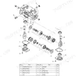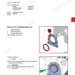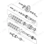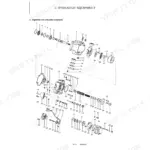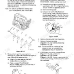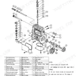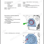


Part of the Yanmar Repair Manuals.
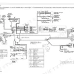
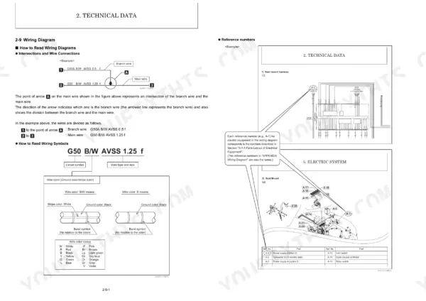
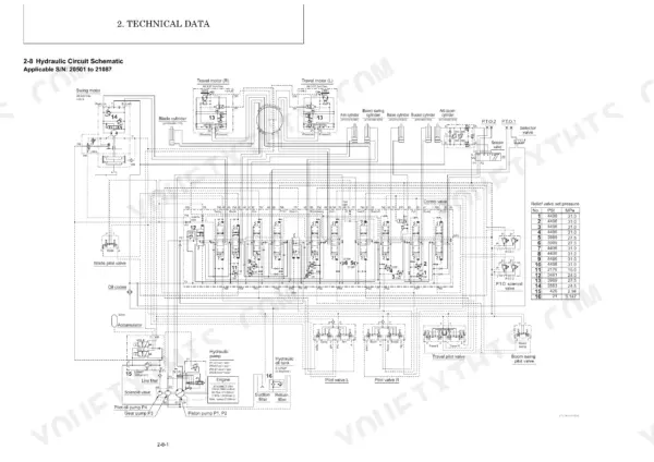
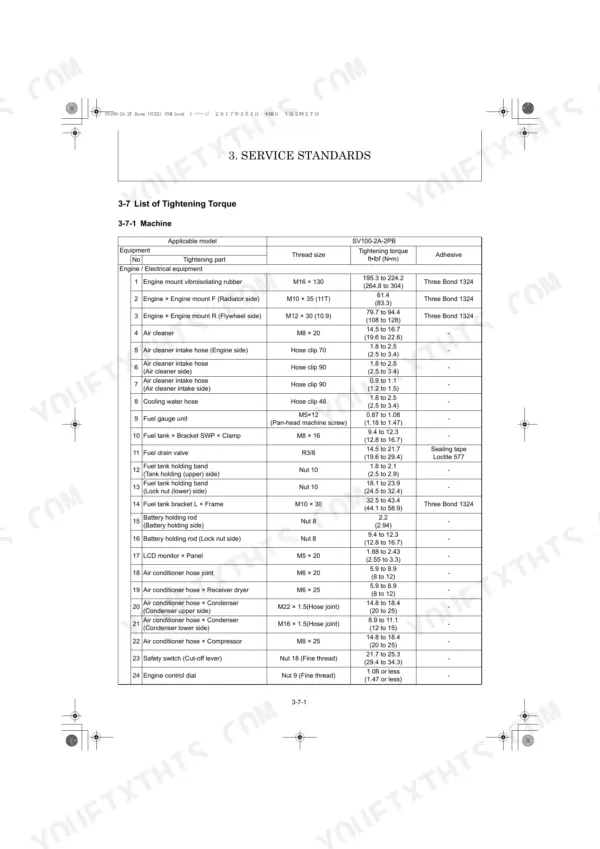
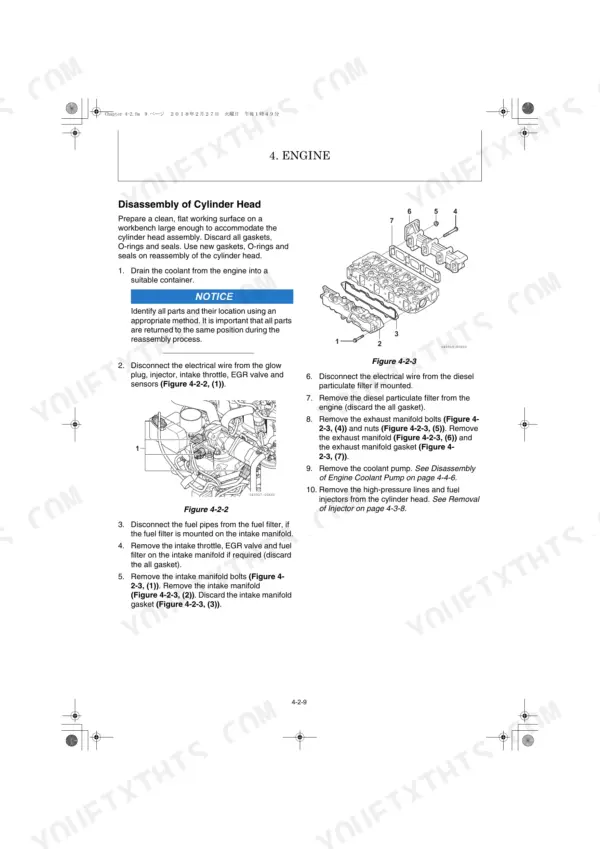
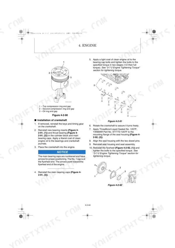
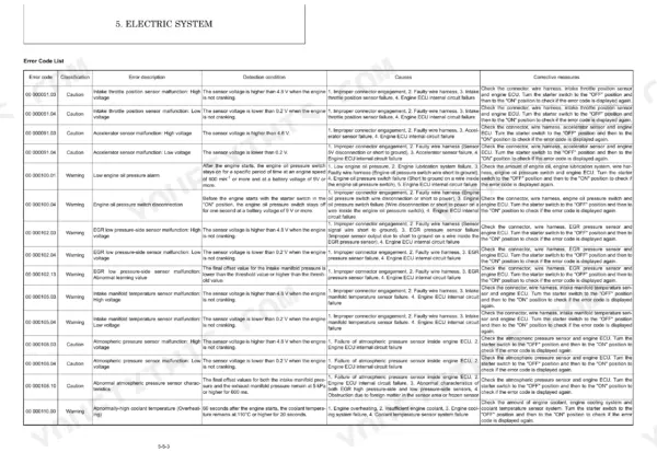
All 745 pages of this Yanmar SV100-2A 2PB Service Manual are built around one machine: the 2015-2018 excavator, from engine internals to hydraulic circuit operation. Inside, you get complete wiring diagrams covering every circuit from engine ECU start/stop logic to the hydraulic controller, plus full hydraulic schematics tracing pump, control valve, swing motor, and travel motor fluid paths. The troubleshooting chapter includes a quick-reference fault table and a full error code library, while the service standards section delivers torque tables, pressure adjustment specs, and exploded views for every major assembly. Engine mount vibroisolating rubber torques to 264.8-304 N•m; the hydraulic pump M5 socket head bolts tighten to 6.9 N•m. Every hour your machine sits costs money. Download this PDF, pull it up on your phone or tablet right at the machine, and let the bookmarks take you to the exact spec in seconds.
What's Inside This Yanmar SV100-2A (2PB) Manual
| System | Pages | Key Topics |
|---|---|---|
| General Cautions for Maintenance Work | 14-25 | 1-1 Correct Work, 1-2 Safety Precautions, 1-3 Preparations, 1-4 Cautions for Disassembly and Reassembly, 1-5 Cautions for Removal and Installation of Hydraulic Equipment |
| Technical Data | 26-53 | 2-1 Specifications, 2-2 Outline Drawing and Working Area, 2-3 Weight List of Main Parts, 2-4 Lifting Capacity List, 2-5 Specifications for Attachment |
| Service Standards | 54-81 | 3-1 Machine Performance, 3-2 Engine, 3-3 Undercarriage, 3-4 Controls, 3-5 Hydraulic Equipment, 3-6 Implement, 3-7 List of Tightening Torque, 3-8 Pressure Adjustment |
| Engine | 82-266 | 4-1 Safety, 4-2 Engine, 4-3 Fuel System, 4-4 Cooling System, 4-5 Lubrication System, 4-6 Turbocharger, 4-7 Starter Motor, 4-8 Alternator |
| Electric System | 267-327 | 5-1 Electric Equipment of Machine, 5-2 Circuit Description of Engine Start and Stop, 5-3 Engine ECU (Engine Controller), 5-4 Hydraulic ECU (Controller), 5-5 Error Code |
| Hydraulic System | 328-585 | 6-1 Outline, 6-2 Circuit Operation, 6-3 Hydraulic Pump, 6-4 Control Valve, 6-5 Pilot Valve, 6-6 Swing Motor, 6-7 Travel Motor, 6-8 Cutoff Valve |
| Adjustment and Repair | 586-731 | 7-1 Engine and Electric Equipment, 7-2 Undercarriage, 7-3 Controls, 7-4 Swing Bearing, 7-5 Hydraulic Equipment, 7-6 Implement, 7-7 Cabin, 7-8 Air Conditioner |
| Troubleshooting | 732-741 | 8-1 Non-Breakdowns, 8-2 Quick Reference Table for Troubleshooting |
| Appendix | 742-745 | Wiring Diagram |
Quick Reference Specifications
| Specification | Value | Page |
|---|---|---|
| Engine mount vibroisolating rubber tightening torque | 195.3 to 224.2 ft•lbf (264.8 to 304 N•m) | p. 70 |
| Hydraulic pump theoretical discharge volume | 2.26 (37) × 2, 1.67 (27.4) × 1, 0.58 (9.5) × 1 cu.in./rev (cu.cm/rev) | p. 27 |
| Hydraulic pump hexagon socket head bolt M5 tightening torque | 5.1 ft•lbf (6.9 N•m) | p. 75 |
| Suction filter filtration accuracy | 105 μ | p. 29 |
| Return filter filtration accuracy | 10 μ | p. 29 |
| Air cleaner filtration area | 20.8 sq.ft. (1.93 sq.m) | p. 31 |
| Maximum air intake restriction | 0.90 psi (6.23 kPa; 635 mmAq) | p. 92 |
| LO filter filtration area | 180 sq.in. (1160 sq.cm) | p. 31 |
| LO filter valve opening pressure | 11.4 to 17.1 PSI (0.08 to 0.12 MPa) | p. 31 |
| Radiator cap pressure | 12.80 PSI (0.09 MPa) | p. 31 |
| Engine mount F (Radiator side) M10 × 35 (11T) tightening torque | 61.4 ft•lbf (83.3 N•m) | p. 70 |
| Greasing points periodic inspection | Daily | p. 37 |