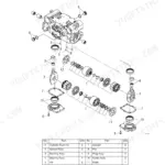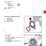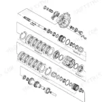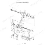



Part of the Yanmar Repair Manuals.
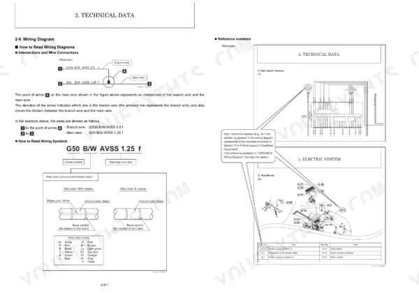
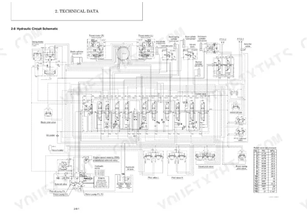
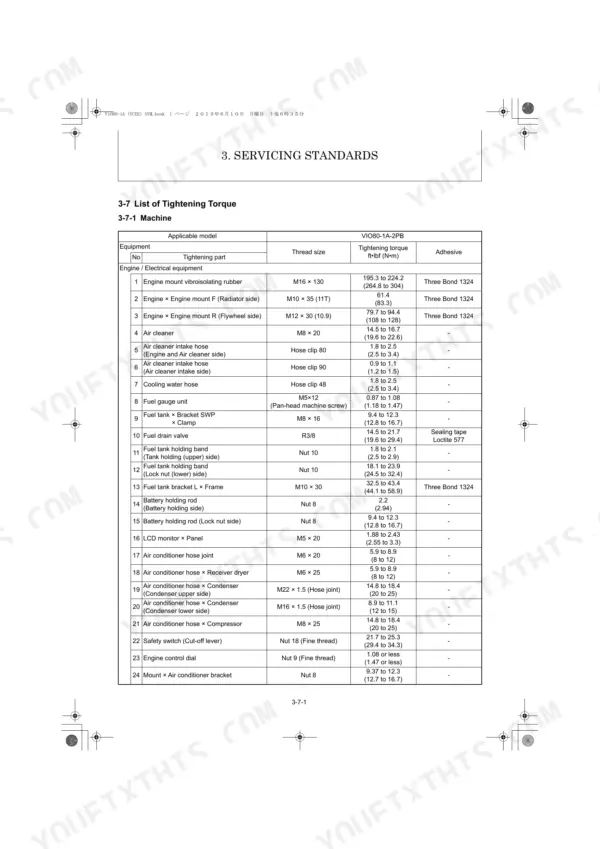
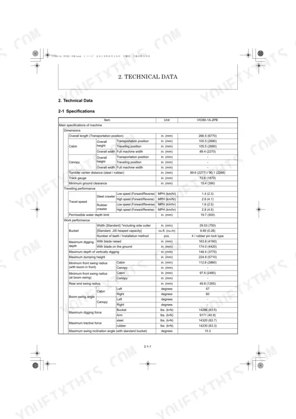
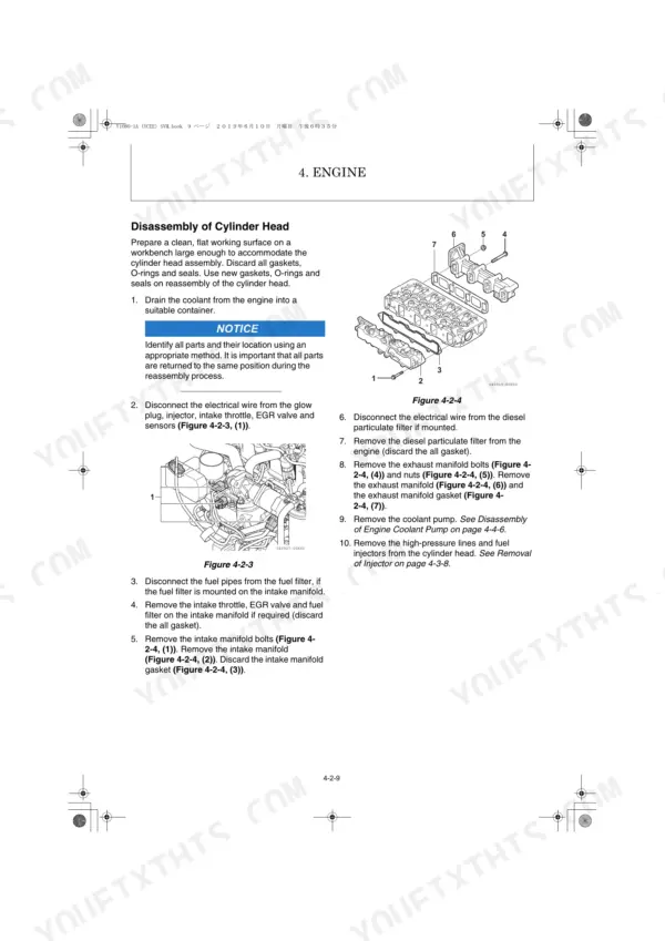
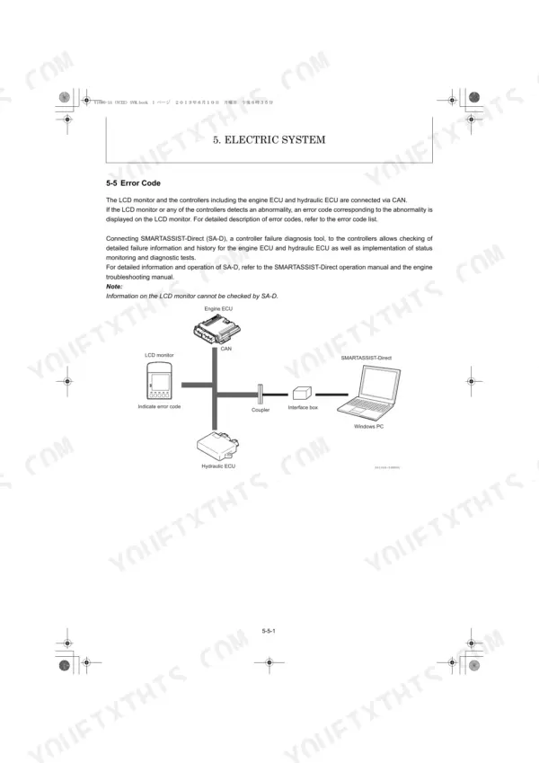
All 745 pages of this Yanmar ViO80-1A Service Manual (OEM #MMB11CENMA-H0100) focus exclusively on the ViO80-1A and ViO80-1A-2PB hydraulic excavators, delivering factory procedures from engine ECU diagnostics to full hydraulic system rebuild. Inside: hydraulic circuit schematics with full fluid routing, wiring diagrams covering the engine controller and hydraulic ECU, a dedicated error code section, and torque tables spanning every major fastener on the machine. You get service standards for undercarriage and controls, swing and travel motor teardown procedures, ESS proportional solenoid valve specs, and a troubleshooting quick-reference table built from real fault patterns. Change the aspiration filter at 100 hours, the hydraulic oil return filter at 250, and bump both intervals to 500 if you're running a hydraulic hammer. No more chasing hydraulic faults with a pressure gauge and a guess. Download the PDF, bookmark your section, and have the right number before you open a valve.
What's Inside This Yanmar ViO80-1A, ViO80-1A-2PB Manual
| System | Pages | Key Topics |
|---|---|---|
| General Cautions for Maintenance Work | 12-23 | Correct Work, Safety Precautions, Preparations, Cautions for Disassembly and Reassembly, Cautions for Removal and Installation of Hydraulic Equipment |
| Technical Data | 24-49 | 2-1 Specifications, 2-2 Outline Drawing and Working Area, 2-3 Weight List of Main Parts, 2-4 Lifting Capacity List, 2-5 Specifications for Attachment |
| Service Standards | 50-77 | 3-1 Machine Performance, 3-2 Engine, 3-3 Undercarriage, 3-4 Controls, 3-5 Hydraulic Equipment, 3-6 Implement, 3-7 List of Tightening Torque, 3-8 Pressure Adjustment |
| Engine | 78-236 | 4-1 Safety, 4-2 Engine, 4-3 Fuel System, 4-4 Cooling System, 4-5 Lubrication System, 4-6 Starter Motor, 4-7 Alternator, 4-8 Electronic Control System |
| Electric System | 237-297 | 5-1 Electric Equipment of Machine, 5-2 Circuit Description of Engine Start and Stop, 5-3 Engine ECU (Engine Controller), 5-4 Hydraulic ECU (Controller), 5-5 Error Code |
| Hydraulic System | 298-583 | 6-1 Outline, 6-2 Circuit Operation, 6-3 Hydraulic Pump, 6-4 Control Valve, 6-5 Pilot Valve, 6-6 Swing Motor, 6-7 Travel Motor, 6-8 Ess Proportional Solenoid Valve |
| Adjustment and Repair | 584-735 | 7-1 Engine and Electric Equipment, 7-2 Undercarriage, 7-3 Controls, 7-4 Swing Bearing, 7-5 Hydraulic Equipment, 7-6 Implement, 7-7 Cabin, 7-8 Air Conditioner |
| Troubleshooting | 736-745 | 8-1 Non-Breakdowns, 8-2 Quick Reference Table for Troubleshooting |
Quick Reference Specifications
| Specification | Value | Page |
|---|---|---|
| Aspiration filter replacement interval | Every 100h (or every 500h if hydraulic hammer is used) | p. 36 |
| Hydraulic oil return filter replacement interval | Every 250h (or every 500h if hydraulic hammer is used) | p. 36 |
| Cab filters replacement interval | Every 250h (or every 500h if used at dusty worksites) | p. 36 |
| Possible causes for weak implement force or slow speed | Hydraulic pump, Control valve, System relief valve, Circuit relief valve, Pilot valve | p. 38 |
| Overall length (Transportation position) | 266.5 in. | p. 24 |
| Maximum digging force (Bucket) | 14286 lbs. | p. 24 |
| Swing speed | 9 rpm | p. 25 |
| Hydraulic pump (Number of pumps) | 4 pcs. | p. 25 |
| System relief set pressure (P1, P2) | 3698 PSI | p. 25 |
| Hydraulic oil tank (Tank capacity) | 31.1 Gals | p. 27 |
| Engine total displacement | 202.5 cu.in. | p. 28 |
| Rated output / engine speed | 56.9 HP / 2000 rpm | p. 28 |