


This is the David Brown Service Repair Manual covering the Cropmaster, 30C, 30D, 25, 25D and 900 tractors, 180 pages of factory workshop procedures for these vintage diesel, kerosene and gasoline machines.It walks through the full drivetrain and running gear: diesel and petrol engine overhaul, clutch and gearbox, the rear axle with its brakes and reduction units, the hydraulic power lift and linkage, front axle and steering, the main frame, and the electrical system with battery testing. Torque figures, clearances and adjustment values are given throughout, including diesel valve clearance and hydraulic lift pressures.With it you can diagnose a hard-starting engine, adjust the clutch, rebuild a tired gearbox, or restore a weak lift instead of guessing your way through a rebuild. Delivered as a downloadable PDF you can read on any device or print.
What's Inside This David Brown CROPMASTER & variants Manual
| System | Pages | Key Topics |
|---|---|---|
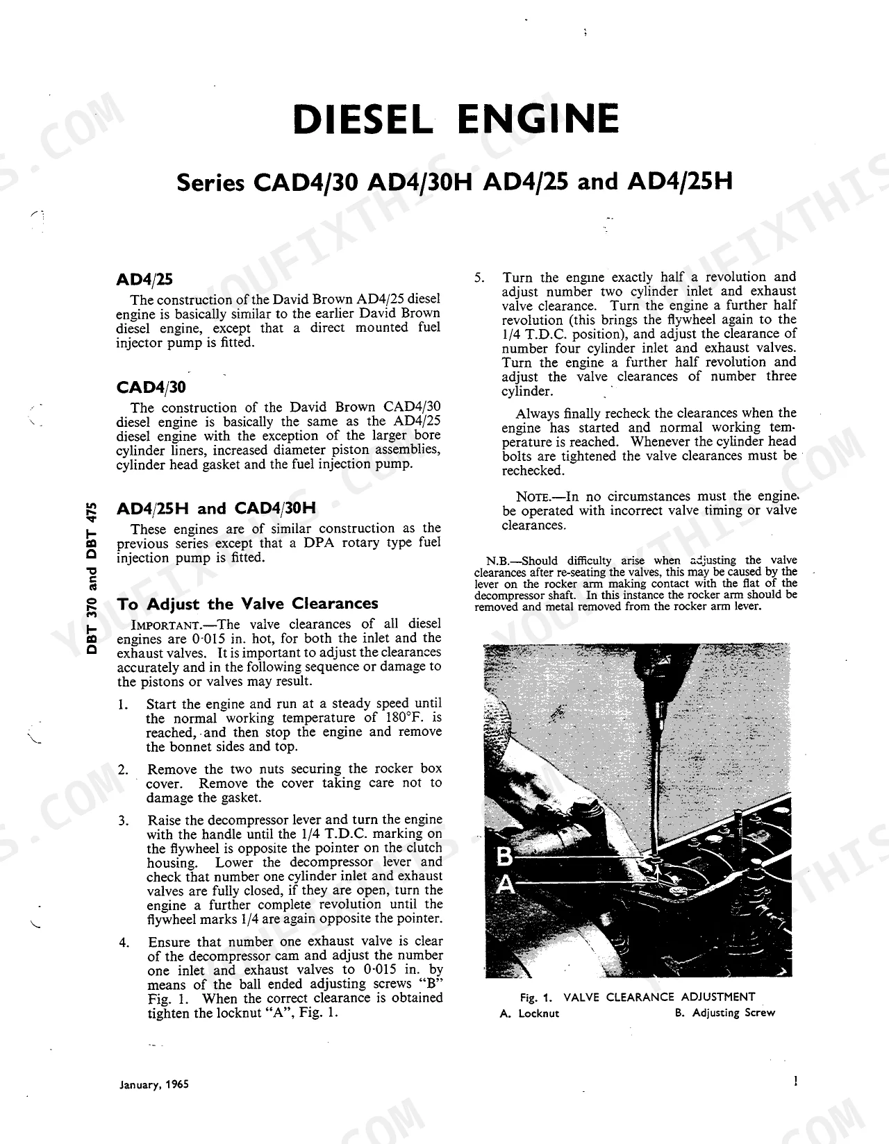
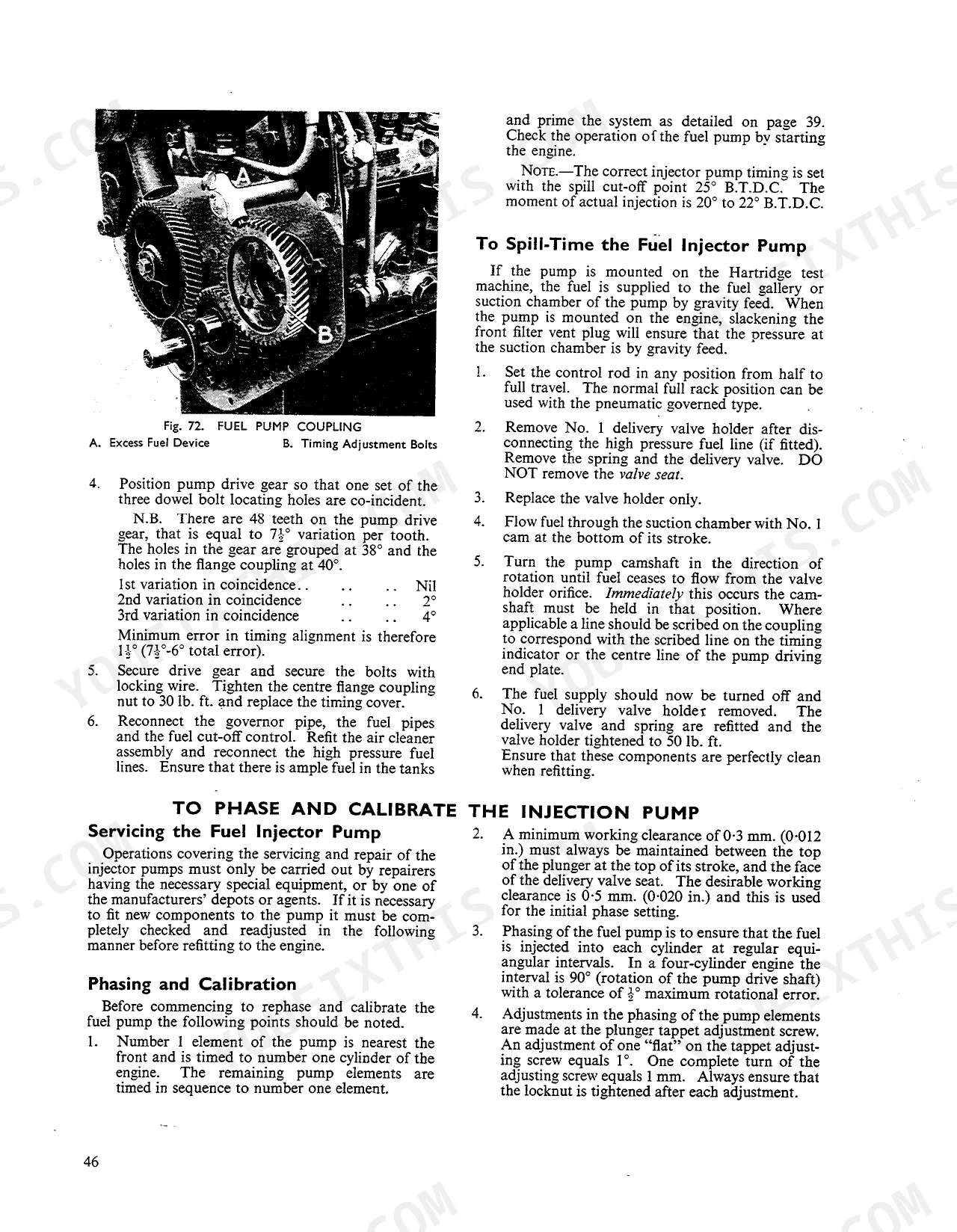
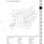
| Diesel Engine | 5-54 | Diesel, Ad4/25, Cad4/30, AD4/25H and CAD4/30H |
| Kerosene and Gasoline Engines | 55-80 | Kerosene Engine Service, Gasoline Engine Service, Fuel System, Carburetor |
| Clutch | 81-88 | To Adjust the Clutch Pedal |
| Gearbox and Differential | 89-100 | To Drain and Refill the Gearbox (Drain Hot Oil, i.e., After a Run., Drain Plug Is in the Centre of the Rear Axle on All Models, An Additional Plug Is Provided on the Detachable Pump Plate on the Bottom of the Gearbox Casing., Remove the Drain Plugs, And Allow to Drain for 10 to 15 Minutes, Then Replace the Plugs., Refill with 4 Gallons of Shell Tractor Oil 50. the Correct Level Is to the Top Mark of the Dipstick.) |
| Rear Axle, Brakes and Reduction Units | 101-112 | Rear Axle, To Adjust the Brakes, To Remove and Replace the Final Drive Shaft and Hub, To Remove and Replace the Final Drive Reduction Assemblies (Nearside Reduction Assembly) |
| Hydraulic System and Lift Linkage | 113-130 | Operation of Hydraulic Power Lift System, Exploded Components of the Hydraulic Pump, Arrangement of the Power Lift, Diagram of the Power Lift in the Lift Position |
| Main Frame and Fittings | 131-138 | Underside View of Main Frame, Top View of Main Frame, Main Frames, Main Frame Components, Lower Hitch Brackets, Seat and Mudguard Support |
| Front Axle and Steering | 139-146 | Front Axle Assembly, Mounting, Sectional Arrangement of Front Axle, Front Axle and Hub Components, To Remove and Replace the Front Axle Assembly |
| Electrical System | 147-180 | Batteries, To Test the Batteries, A Typical Battery Hydrometer, Specific Gravity Readings and Their Indications, Use of Heavy Discharge Meter, Batteries Out of Use |
Quick Reference Specifications
| Specification | Value | Page |
|---|---|---|
| All Models | ||
| Control lever setting gauge clearance | 1/8" to 3/16" | p. 121 |
| By-pass valve control lever clearance | 1/8" to 3/16" | p. 121 |
| Diesel Engines | ||
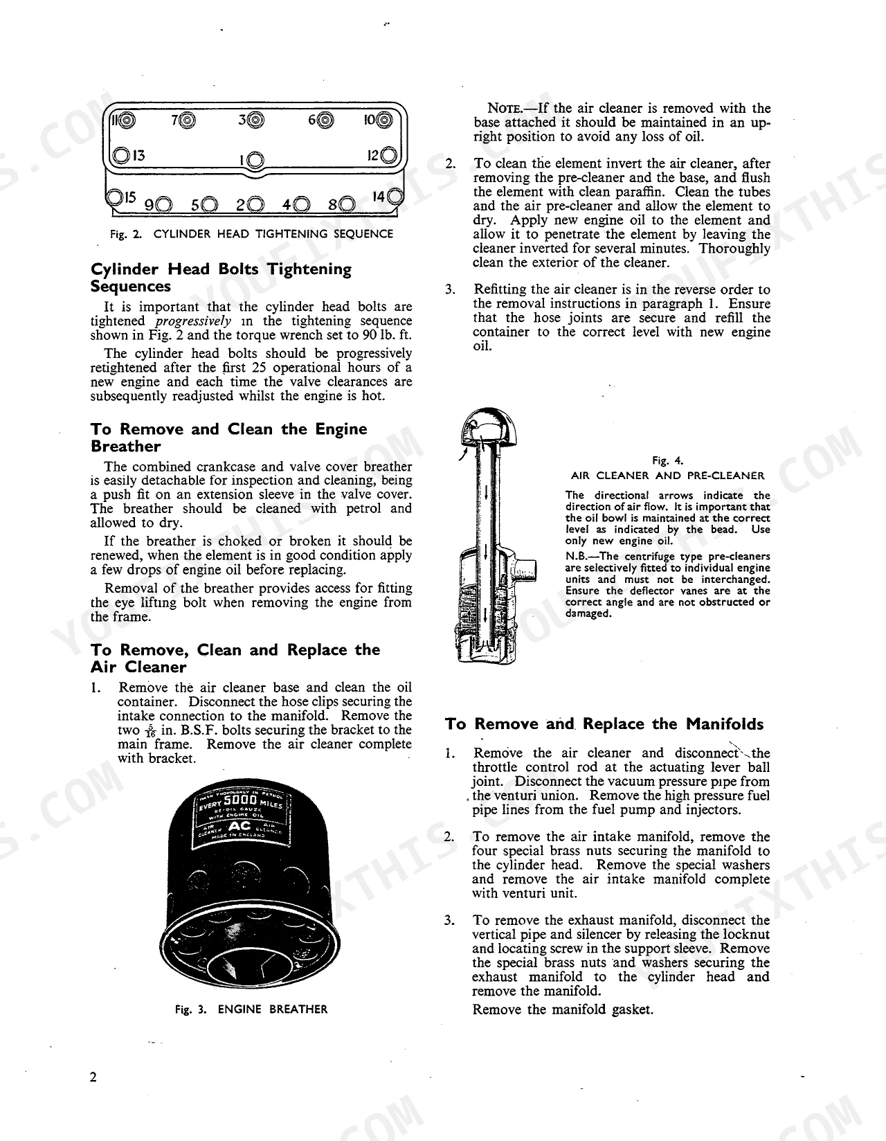
| Cylinder head bolt torque | 90 lb. ft. | p. 6 |
| Fuel filter element replacement interval | Periodically | p. 39 |
| Oil filter element replacement interval | Every 360 operational hours | p. 22 |
| Injector opening pressure (new) | 185 atmospheres | p. 43 |
| Injector opening pressure (used) | 175 atmospheres | p. 43 |
| Kerosene and Gasoline Engines | ||
| Cylinder head bolt torque | 90 lb. ft. | p. 59 |
| Fuel filter gauze cleaning interval | Periodically | p. 78 |
| Oil filter element replacement interval | Every 360 operational hours (every six weeks) | p. 73 |
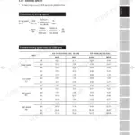
| 25-30 and 900 series tractors | ||
| Clutch pedal free movement | 1/16 in. (1.5 mm.) | p. 82 |
| Clutch pedal free travel (initial adjustment) | 1 in. (2.5 cm.) | p. 82 |
David Brown CROPMASTER & variants Common Problems This Manual Covers
Hard starting or no start
These older diesels start poorly when there is air in the fuel lines, worn injectors, or an injector pump past its best. The manual covers fuel system service and engine timing to trace the cause.
Manual Section: Diesel Engine p. 5Clutch slip or gear clash
A dragging or slipping clutch and difficulty selecting gears usually trace to worn linkage or an out-of-spec pedal adjustment. The clutch section gives the free-travel figures and adjustment steps.
Manual Section: Clutch p. 81Weak or intermittent hydraulic lift
A lift that will not raise implements or drops under load points to pump wear, low or dirty oil, or internal leakage. This section covers the power lift operation, pump, and control valve pressure.
Manual Section: Hydraulic System and Lift Linkage p. 113Oil leaks at gearbox or final drive
Persistent seepage from the gearbox or rear axle on tractors of this age usually means aged seals and gaskets. The gearbox and differential procedures cover draining, refilling and correct oil level.
Manual Section: Gearbox and Differential p. 89Brakes pulling or out of adjustment
Uneven or weak braking is common as linings and adjusters wear. This section explains how to adjust the brakes and service the final drive shaft, hub and reduction assemblies.
Manual Section: Rear Axle, Brakes and Reduction Units p. 101Engine overheating or coolant loss
Overheating on these engines often comes back to a stuck thermostat, cooling blockage or water pump wear. The engine section covers cooling components and the thermostat full-open temperature.
Manual Section: Diesel Engine p. 5Weak battery or charging faults
Slow cranking and flat batteries are a frequent complaint on restoration machines. The electrical section covers battery testing, hydrometer readings and heavy discharge testing.
Manual Section: Electrical System p. 147Frequently Asked Questions
Which tractors and engines does this manual cover?
It covers the David Brown Cropmaster, 30C, 30D, 25, 25D and 900 tractors, including the AD4/25, CAD4/30, AD4/25H and CAD4/30H diesel engines plus the kerosene and gasoline versions.
Does it cover diesel engine overhaul and valve clearances?
Yes. The Diesel Engine section covers overhaul of the AD4/25 and CAD4/30 engines, including valve clearance adjustment and the tightening sequences you need for a rebuild. p. 5
Does it include hydraulic lift service and pressures?
Yes. The Hydraulic System and Lift Linkage section explains power lift operation, the pump, and the main control valve pressure so you can diagnose a weak or slow lift. p. 113
Is the electrical system and battery testing included?
Yes. The Electrical System section covers the batteries, hydrometer testing, specific gravity readings and use of a heavy discharge meter. p. 147
What format is this manual in?
This manual ships as a 180-page searchable PDF that downloads the moment checkout completes. Open it on a laptop, tablet, or phone and carry it straight to the shop floor.
Can I print specific sections of this manual?
No restrictions apply: the PDF is DRM-free. Print whatever sections you want to take to the shop, on standard letter or A4 paper.
Can I find wiring schematics in this David Brown CROPMASTER & variants manual?
Yes, this David Brown CROPMASTER & variants Service Repair Manual includes complete electrical wiring diagrams and circuit layouts for CAV and Lucas electrical systems.


Reviews
There are no reviews yet.