


![John Deere 355D Repair Manual [Lawn & Garden Tractor]](https://youfixthis.com/wp-content/uploads/2012/02/Manual_Download-300x300.jpg)
Part of the John Deere Repair Manuals.
This is the complete John Deere factory repair manual for the 410B, 410C, 510B and 510C Backhoe Loaders. Across 1,056 pages it covers every major system on all four machines: removing and rebuilding the diesel engine, servicing the transmission and differential, repairing the main hydraulic pump and control valves, fixing loader and backhoe attachment cylinders, and tracing the full electrical system with wiring diagrams. It is the same document a John Deere dealer technician works from, with the torque values, capacities and test pressures called out so each repair is done to spec the first time.
What's Inside This John Deere 410B-510C Repair Manual
| System | Pages | Key Topics |
|---|---|---|
| General Information | Safety Information, Identification Number Location, General Specifications, Torque Values, Lubrication, Inspection Procedures, Fuels and Lubricants | |
| Wheels | Powered Wheels and Fastenings, Non-Powered Wheels and Fastenings, Tire Pressures, Wheel Weight Ballast | |
| Axles and Suspension | Non-Powered Wheel Axles, Axle Shafts, Bearings and Reduction Gears | |
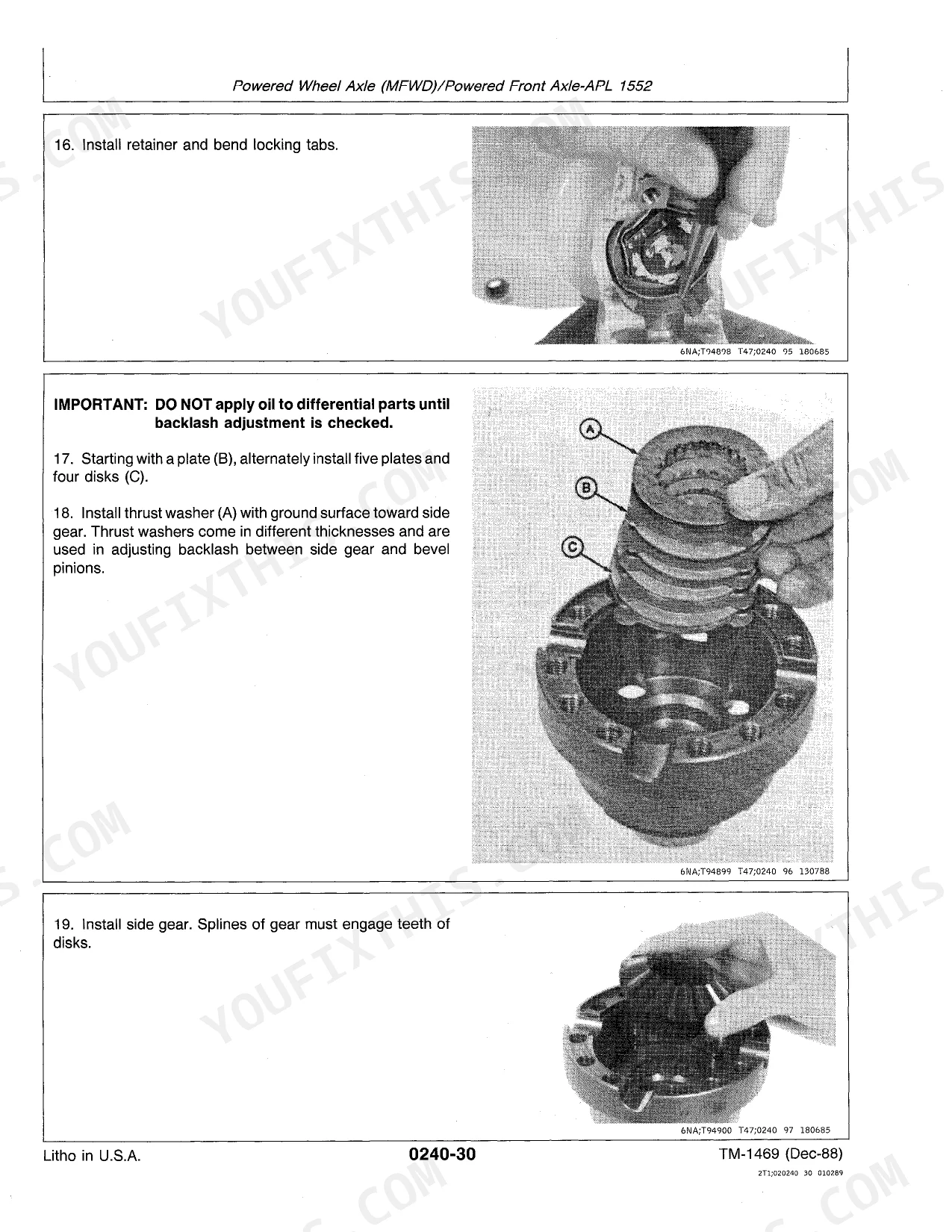
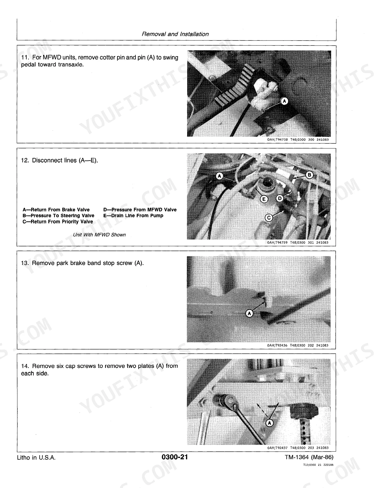
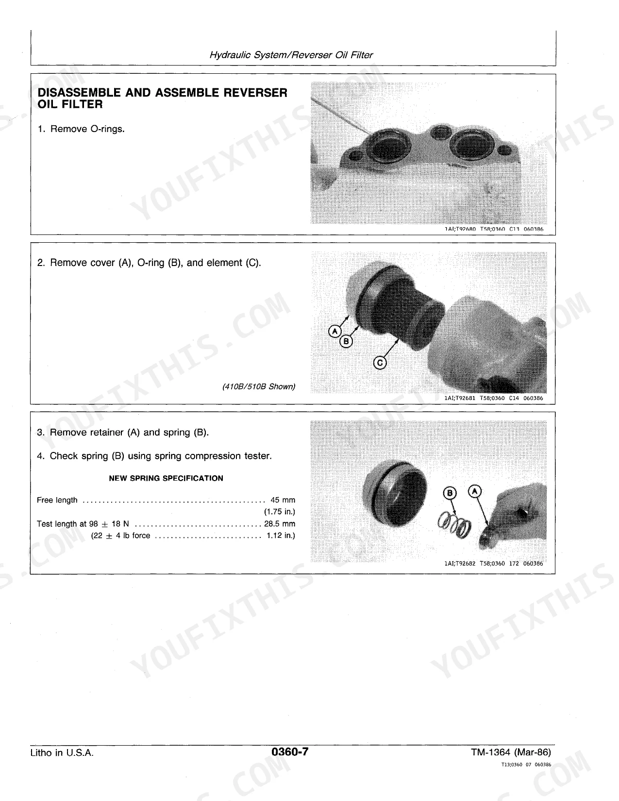
| Transmission | Removal and Installation, Controls, Input Drive Shafts and U-Joints, Gears, Shafts, Housings, Bearings, Differential Lock, Brake and Park Brake, Hydraulic System, Control Valve, Suction Screen, Oil Pump, Lubrication System | |
| Engine | Removal and Installation, Fuel Injection System, Intake Manifold, Turbocharger, Water Pump, Thermostats, Housing and Water Piping, Oil Cooler, Fuel Filter, Fuel Transfer Pump, Starting Motor and Fastenings | |
| Engine Auxiliary Systems | Cold Weather Starting Aids, Cooling System, Speed Controls, Intake System, External Fuel Supply Systems | |
| Steering System | Hydraulic Steering Valve, Steering Cylinder | |
| Service Brakes | Active Elements, Brake Disks and Control Linkage, Hydraulic Brake Valve | |
| Park Brakes | Active Elements, Controls Linkage | |
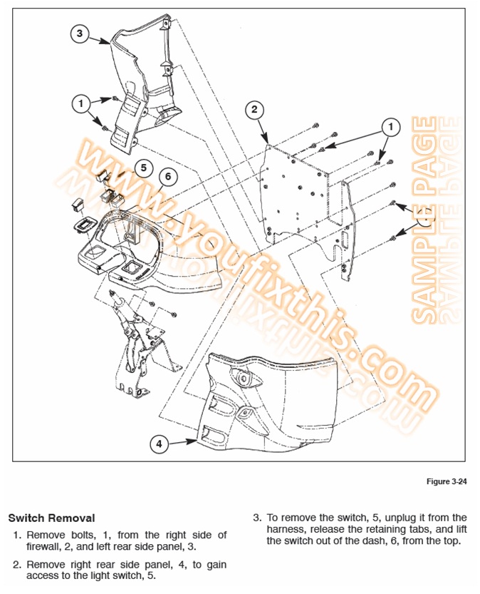
| Electrical System | Batteries, Support and Cables, Alternator, Regulator and Charging System Wiring, Lighting System, Wiring Harness and Switches, System Controls, Instruments, Indicators and Senders, Motors and Actuators | |
| Frame and Chassis | Frame Installation, Chassis Weights | |
| Operator's Station | Removal and Installation, Operator Enclosure, Wiper Motor and Windshield Washer, Seat and Seat Belt, Heating and Air Conditioning | |
| Main Hydraulic System | Main Hydraulic Pump, Pump Drive, Hydraulic Filter, Oil Cooler, Oil Cooler Bypass Valve, System Relief Valve | |
| Loader | Removal and Installation, Buckets, Controls Linkage, Frames, Hydraulic Control Valve and Cylinders | |
| Backhoe | Buckets, Controls Linkage, Frames, Hydraulic Control Valve and Cylinders, Boom and Stick Repair |
Quick Reference Specifications
| Specification | Value | Page |
|---|---|---|
| 410B, 410C, 510B, 510C | ||
| Rear wheel assembly weight (without fluid ballast) | 141 kg (310 lb) | |
| Rear wheel assembly weight (with fluid ballast) | 420 kg (930 lb) | |
| Rear wheel to axle cap screw torque | 575 + 170 - 115 N·m (424 + 125 - 85 lb-ft) | |
| 410B, 410C | ||
| Rear tire pressure (16.9 L x 24 8 PR R4) | 221 kPa (2.2 bar / 32 psi) | |
| Rear tire pressure (19.5 L x 24 10 PR R4) | 193 kPa (1.9 bar / 28 psi) | |
| Rear tire pressure (21 L x 24 10 PR R4) | 179 kPa (1.8 bar / 26 psi) | |
| 510B, 510C | ||
| Rear tire pressure (F/19.5 L x 24 10 PR) | 193 kPa (2.0 bar / 28 psi) | |
| Rear tire pressure (F/19.5 L x 24 12 PR) | 193 kPa (2.0 bar / 28 psi) | |
John Deere 410B-510C Common Problems This Manual Covers
Complete or intermittent loss of hydraulic power when operating the loader or backhoe
Start by checking the main hydraulic pump for internal wear and inspecting the system relief valve for a setting that is too low or a valve that is stuck open. The Main Hydraulic System section covers pump removal, pump drive inspection and the relief valve test procedure. Check the hydraulic filter and oil cooler bypass valve before condemning the pump, as a clogged filter or stuck bypass valve can starve the circuit and mimic a failed pump.
Manual Section: Main Hydraulic SystemEngine stalls under load or cannot reach rated RPM during digging or lifting
Fuel restriction is the first thing to eliminate - replace the fuel filter, bleed air from the fuel system and verify the fuel transfer pump is delivering adequate flow at the injection pump inlet. The Engine section covers the complete fuel injection system, fuel transfer pump and intake manifold inspection. If fuel delivery is correct, check the air intake for restriction before testing injection pump output pressure.
Manual Section: EngineGrinding or slipping when engaging gears, or refusal to shift between forward and reverse
Transmission clutch plates are the most common failure point on high-hour B-series and C-series machines. The Transmission section covers complete disassembly including input drive shaft removal, clutch plate inspection and clearance measurement, and the hydraulic control valve rebuild. Measure clutch pack clearance before assuming the plates are worn - a sticking control valve spool can give the same symptom as a worn pack.
Manual Section: TransmissionHydraulic leaks at the backhoe boom or stick cylinder joints requiring repeated seal replacement
Cylinder rod seal failure at the boom and stick joints accelerates when the chrome rod surface is pitted or scored. The Backhoe section covers cylinder removal, rod inspection and the seal replacement procedure. Inspect the rod surface for scoring before installing new seals - a damaged rod will cut the new seals within hours. Replace the rod if the chrome surface shows pitting deeper than a fingernail scratch.
Manual Section: BackhoeFrequently Asked Questions
Does this manual cover all four models - 410B, 410C, 510B and 510C?
Yes, this is the combined factory repair manual for all four machines. The 410B and 510B are the earlier B-series loaders, and the 410C and 510C are the updated C-series. The manual identifies where procedures differ between models and where all four share the same spec or repair step.
Why does the backhoe lose power or drop under load?
Intermittent power loss under backhoe load is most often traced to the main hydraulic pump or a worn relief valve allowing pressure to bleed off before reaching the boom cylinders. The Main Hydraulic System section covers removing and testing the pump, checking the system relief valve setting, and inspecting the oil cooler bypass valve so you can find the pressure drop before swapping parts.
What causes transmission grinding or failure to engage gears on the 410C and 510C?
Grinding on gear changes usually points to worn clutch plates, a damaged differential component, or low hydraulic pressure in the transmission control circuit. The Transmission section covers the full clutch plate removal sequence, differential inspection and the hydraulic control valve so you can confirm which component is at fault before ordering parts.
Why does the engine stall or lose power under load?
Fuel starvation is the most common cause - a clogged fuel filter or a failing fuel transfer pump starves the injectors under demand. The Engine and Engine Auxiliary sections cover the fuel injection system, fuel transfer pump, intake system and external fuel supply so you can verify fuel delivery, check for air in the system and service the injectors if needed.
Does this manual include wiring diagrams and electrical troubleshooting?
Yes. The Electrical System section covers batteries, alternator and charging system wiring, the full wiring harness and connectors, lighting, instruments and indicator senders, and the motor and actuator circuits. Wiring diagrams are included so you can chase intermittent faults like burnt connectors or a failing alternator without guessing which wire goes where.
How will I receive this John Deere 410B, 410C, 510B, 510C Repair?
A 1056-page Repair in searchable PDF format (134 MB), available the moment you complete checkout. View on computer, tablet, or phone, with no shipping wait.
Can I print specific sections of this John Deere 410B, 410C, 510B, 510C Repair?
No restrictions at all. Print individual pages, full chapters, or the entire manual. The PDF is completely unlocked.


Reviews
There are no reviews yet.