


Part of the John Deere Repair Manuals.
This is the John Deere repair technical manual for the 5055E, 5065E and 5075E tractors, manual number TM900919, dated July 2013 and written in English. These utility tractors use the turbocharged 3029T diesel engine, and the manual covers both the 9x3 TSS and 12x12 PowrReverser transmissions, in open station and cab forms.Across 790 pages, technicians can work through engine repair, the fuel, air intake and exhaust systems, electrical repair, both power train options, steering and brake repair, hydraulic repair, and the operator station. It gives specifications, service parts kits, wear tolerances and torque values, with many figures verified against the manual.Repair sections tell how to fix the components, while the general information covers safety, fuels and lubricants and serial numbers. It is delivered as a downloadable PDF you can read on any device or print the pages you need in the shop.
What's Inside This John Deere 5055E, 5065E, 5075E Repair Manual
| System | Pages | Key Topics |
|---|---|---|
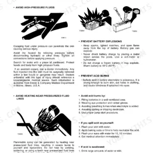
| General Information | 8-102 | Safety (Recognize Safety Information, Understand Signal Words, Follow Safety Instructions, Handle Fluids Safely, Avoid Fires, Prevent Battery Explosions) |
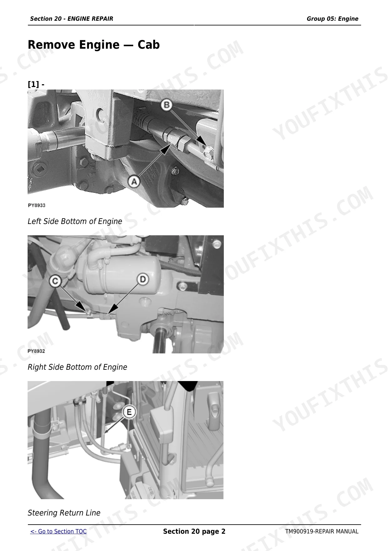
| Engine Repair | 103-164 | Engine (Service Equipment and Tools, Specifications, John Deere Engine Repair, Use Ctm, Remove Engine, Cab) |
| Fuel, Air Intake and Exhaust Systems | 165-193 | Fuel System (Special or Essential Tools, Injection Pump, Nozzle and Governor Repair, Use Ctm, Remove, Inspect and Install Fuel Tank) |
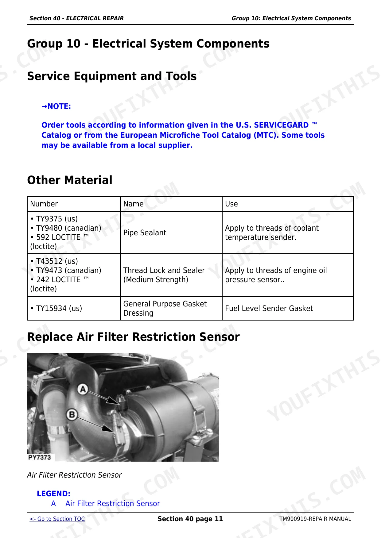
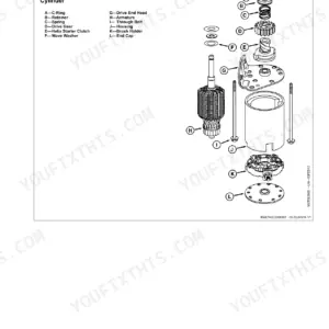
| Electrical Repair | 194-276 | Battery, Starter and Alternator (Starter Repair, Use Ctm, Remove and Install Battery, Remove and Install Starter, Replace Alternator/Regulator) |
| Power Train Repair (12X12 Pr Transmission) | 277-323 | Clutch Housing (John Deere Transmission Repair, Use Ctm, Specifications, Separate Engine From Clutch Housing, Install Engine to Clutch Housing, Remove) |
| Power Train Repair (9X3 TSS Transmission) | 324-400 | Clutch Housing (John Deere Transmission Repair, Use Ctm, Service Equipment and Tools, Other Material, Essential Tools, Specification) |
| Steering and Brake Repair | 401-468 | Steering Repair (Other Material, Specifications, Service Parts Kits, Remove and Install Steering Column and Valve, Disassemble and Inspect Steering Valve - Sauer Danfoss, Assemble Steering Valve - Sauer Danfoss) |
| Hydraulic Repair | 469-564 | Hydraulic Pump and Filter (Essential Tools, Specifications, Service Parts Kits, Remove, Inspect, And Install Hydraulic Oil Pick-Up Screen) |
| Miscellaneous Repair | 565-592 | Front Axle (Specification, Remove and Install Front Axle, MFWD), Wheels (Specifications, Inspect and Replace Front Wheel Bearings, Tighten Bolts, Rear Axle) |
| Operator Station Repair (Oos) | 593-622 | Seat and Support (Remove and Install Seat and Support, Disassemble, Inspect and Assemble Seat and Seat Switch) |
| Operator Station Repair (Cab) | 623-790 | Seat and Support, Remove and Install Seat and Support (Cab), Control Console and Panel, Remove and Install Right-Side Control Console, Remove and Install Left-Side Control Console, Cab Components, Essential Tools, Service Equipment and Tools |
Quick Reference Specifications
| Specification | Value | Page |
|---|---|---|
| Front Wheel Cap Screws - MFWD Torque | 310 N·m (229 lb-ft) | p. 572 |
| Rear Axle Disk-to-Flange Torque | 550 N·m (406 lb-ft) | p. 575 |
| Rear Axle Rim-to-Disk Torque | 245 N·m (180 lb-ft) | p. 575 |
| Clutch Yoke Cap Screw Torque (9x3 TSS Transmission) | 65 Nm (48 lb-ft) | p. 343 |
| Clutch Housing to Transmission Cap Screw Torque (9x3 TSS Transmission) | 136 Nm (100 lb-ft) | p. 343 |
| Seat Switch Replacement | Replace as necessary | p. 241 |
| Main Wiring Harness Replacement | Replace if necessary | p. 262 |
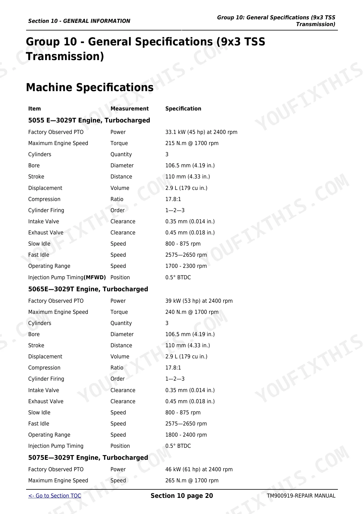
| Engine Bore | 106.5 mm | p. 27 |
| Engine Displacement | 2.9 L | p. 27 |
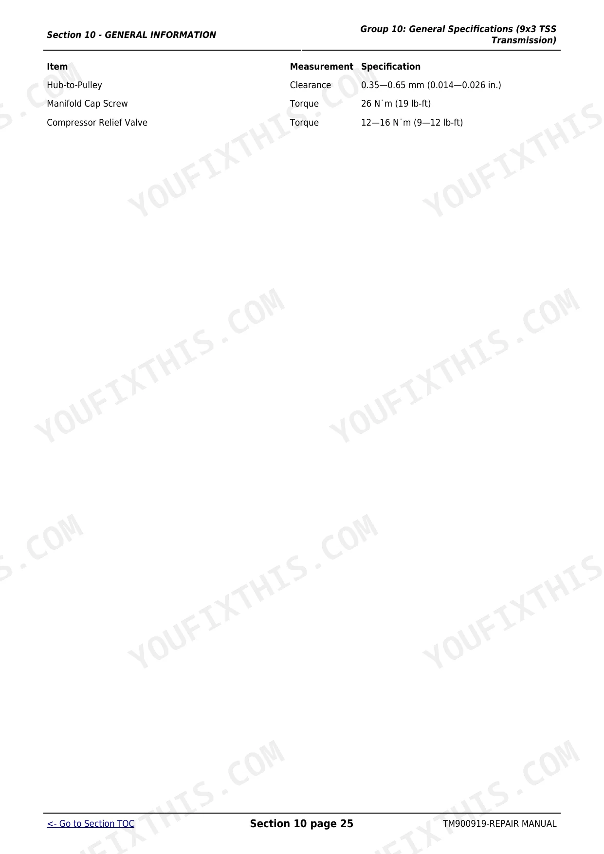
| Intake Valve Clearance | 0.35 mm | p. 27 |
John Deere 5055E, 5065E, 5075E Common Problems This Manual Covers
Weak movement from a stop
A tractor that struggles to move from a stop or feels like the clutch is riding is commonly fixed by correcting clutch pedal free play. The 12x12 PowrReverser power train section covers the clutch housing, pedal and linkage service.
Manual Section: Section 50 - Power Train Repair (12X12 Pr Transmission) p. 277Tractor will not move
No movement or intermittent drive on these tractors often traces to the seat switch, neutral safety switch, relays or a pinched main wiring harness. The electrical repair section covers the battery, wiring harness and related components.
Manual Section: Section 40 - Electrical Repair p. 194Hard starting or no start
Hard starting or a no start that clears after bleeding usually means air in the fuel system, a clogged filter, or a closed fuel shut off. The fuel, air intake and exhaust section covers the injection pump, fuel tank and related service.
Manual Section: Section 30 - Fuel, Air Intake and Exhaust Systems p. 165Overheating and power loss
Overheating or loss of power often starts with a dirty radiator core or grille screens, low coolant, or a loose fan belt. The engine repair section covers the engine and its cooling system service and specifications.
Manual Section: Section 20 - ENGINE REPAIR p. 103Heavy steering or brake faults
Steering that becomes heavy or brakes that feel weak call for work on the steering valve, cylinder or brake components. The steering and brake repair section covers the Sauer Danfoss and Eaton steering valves, the steering cylinder and tie rods.
Manual Section: Section 60 - Steering and Brake Repair p. 401Weak or slow hydraulics
Slow or weak hydraulic response points to the pump, filter or pickup screen. The hydraulic repair section covers removing and inspecting the pickup screen, the hydraulic pump disassembly and assembly, and the oil filter and manifold.
Manual Section: Section 70 - Hydraulic Repair p. 469Frequently Asked Questions
Which John Deere tractors does this manual cover?
It covers the John Deere 5055E, 5065E and 5075E tractors with the turbocharged 3029T engine, including both the 9x3 TSS and 12x12 PowrReverser transmissions and open station and cab versions. It is manual TM900919.
What are the wheel and lug nut torque values?
The miscellaneous repair section gives verified figures, including 310 N.m (229 lb-ft) for the MFWD front wheel cap screws and 550 N.m (406 lb-ft) for the rear axle disk to flange bolts. p. 565
Does it cover clutch adjustment?
Yes. The power train repair section covers the clutch housing, pedal and linkage, including clutch yoke and housing cap screw torques, so you can service and adjust the clutch. p. 277
Does it include full engine internal specs?
The engine repair section covers removing, installing and servicing the engine, though some internal specifications such as cylinder head torque refer you to the separate John Deere component technical manual (CTM). p. 103
What do I get after purchasing this John Deere 5055E, 5065E, 5075E manual?
A 790-page searchable PDF, ready to download the moment you check out. It opens on any device, so you can pull it up on your phone right at the tractor. No shipping, no waiting.
Are there any print restrictions on this manual?
No restrictions at all. Print individual pages, full chapters, or the entire manual. The PDF is completely unlocked.


Reviews
There are no reviews yet.