


Part of the John Deere Repair Manuals.
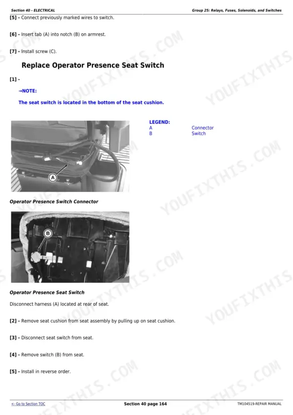
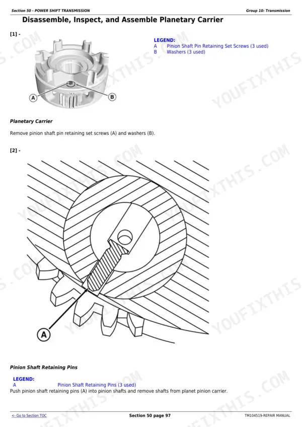
Factory repair manual TM104519 for the John Deere 8295RT, 8320RT and 8345RT rubber-track tractors, serial numbers up to 902500 (2011-2015). This is the wrench-turning book: removal, disassembly, overhaul and installation for every major system, with the actual torque values you need - integrated hydraulic pump housing screws at 205 N·m (150 lb-ft), mid-frame cross brace at 430 N·m (316 lb-ft), pump-to-pump drive housing at 180 N·m (132 lb-ft). It carries two full transmission sections (50 Power Shift, 51 AutoPowr/IVT) plus Section 95 for the track frame, which is where these RT machines live and die. Capacities, sight-glass oil levels and dealer tooling are all in here.
Other edition of this manual
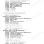
What's Inside This John Deere 8295RT-8345RT Repair Manual
| System | Pages | Key Topics |
|---|---|---|
| General Information (Section 10) | 9-52 | Safety, Torque Method and Charts, Fuels and Lubricants, Oil Line and Fitting Service |
| Engine (Section 20) | 53-68 | Engine Component Removal and Installation, Engine Repair |
| Fuel and Cooling Systems (Section 30) | 69-135 | Diesel Fuel System, Air Intake, Engine Cooling |
| Electrical (Section 40) | 136-350 | Harnesses, Component Location, Sensors, Charging and Starting |
| Power Shift Transmission (Section 50) | 351-480 | Power Shift Transmission Removal, Overhaul, Clutch Packs, Assembly Torques |
| Autopowr/Ivt Transmission (Section 51) | 481-676 | AutoPowr / IVT Continuously Variable Transmission Overhaul and Assembly |
| Drive Systems (Section 56) | 677-837 | Final Drives, Axles, Differential, PTO |
| Steering and Brakes (Section 60) | 838-929 | Steering Pump and Valve, Service and Park Brakes |
| Hydraulics (Section 70) | 930-1021 | Integrated Hydraulic Pump, Clean-Oil Reservoir 23 L, Valve Stack, Hitch, Assembly Torques |
| Miscellaneous (Section 80) | 1022-1037 | Frame, Ballast, Miscellaneous Service |
| Operator Station (Section 90) | 1038-1123 | Cab, Seat, HVAC, Controls |
| Track Frame and Components (Section 95) | 1124-1235 | Rubber Track, Idlers, Mid-Rollers, Track Frame, Tensioner - the Rt Undercarriage |
| Dealer Tools (Section 99) | 1236-1338 | John Deere Dealer Service Tools |
Quick Reference Specifications
| Specification | Value | Page |
|---|---|---|
| Integrated Hydraulic Pump-to-Pump Drive Housing Cap Screws Torque | 180 N·m (132 lb-ft) | p. 930 |
| Mid-Frame Bottom Plate Cap Screws Torque | 125 N·m (92 lb-ft) | p. 930 |
| Mid-Frame Cross Brace Cap Screws Torque | 430 N·m (316 lb-ft) | p. 930 |
| Supply Line from Clean Oil Reservoir-to-Integrated Hydraulic Pump Cap Screws Torque | 125 N-m (92 lb-ft) | p. 930 |
| Supply Line-to-Integrated Hydraulic Pump Cap Screws Torque | 70 N·m (52 lb-ft) | p. 930 |
| Transmission Pump-to-Steering Pump Cap Screws Torque | 125 N·m (92 lb.-ft.) | p. 930 |
| Valve Stack-to-Hitch Frame Retaining Nuts Torque | 90 N·m (66 lb-ft) | p. 930 |
| Supply Line-to-Transmission Pump Cap Screws Torque | 105 N·m (78 lb-ft) | p. 944 |
| Valve-to-Steering Filter Assembly Bracket Cap Screws Torque | 46 N·m (34 lb-ft) | p. 944 |
| Hydraulic oil capacity (pump drive housing) | 10 L (2.5 gal) | p. 955 |
| Hydraulic oil capacity (clean-oil reservoir) | 23 L (6 gal) | p. 956 |
| Hydraulic oil level | 20 mm (3/4 in.) above upper level mark in sight glass | p. 956 |
| Integrated Hydraulic Pump Housing Screws Torque | 205 N·m (150 lb-ft) | p. 959 |
| Pump Controller-to-Pump Housing Socket Head Screws Torque | 12 N·m (106 lb-in.) | p. 959 |
| Valve Stack-to-Tractor Mounting Cap Screws Torque | 125 N·m (91 lb-ft) | p. 971 |
John Deere 8295RT-8345RT Common Problems This Manual Covers
Steering goes sluggish or quits under heavy load
Start with hydraulic oil level - it must sit 20 mm (3/4 in.) above the upper sight-glass mark. If level is right, Section 60 walks through steering component removal and overhaul, and Section 70 covers the supply side feeding it.
Manual Section: Steering And Brakes (Section 60) p. 838Hydraulic pump whining, growling or vibrating
Noise usually means the integrated pump is eating itself or starving for oil. Section 70 covers pump removal, teardown and reassembly with the correct fastener values: housing screws to 205 N·m (150 lb-ft), pump-to-pump drive housing to 180 N·m (132 lb-ft).
Manual Section: Hydraulics (Section 70) p. 930SCV or valve stack dead - zero pressure at the couplers
A stuck spool or failed section in the stack blocks flow completely. Section 70 covers valve stack removal, spool and centering spring service, and reassembly torques including tie-bolt nuts at 26 N·m (20 lb-ft) and stack-to-tractor mounting screws at 125 N·m (91 lb-ft).
Manual Section: Hydraulics (Section 70) p. 930Track rollers, idlers or drive wheels worn and getting loud
Undercarriage wear is the number one cost on an RT, and letting a rough roller run destroys the belt. Section 95 gives removal, inspection and installation procedures for rollers, idlers, drive wheels and the track frame itself, so you can rebuild instead of guessing.
Manual Section: Track Frame And Components (Section 95) p. 1124Frequently Asked Questions
Does this manual cover my serial number?
The cover states 8295RT, 8320RT and 8345RT up to serial number 902500. Check your serial plate before buying. If your tractor is above that break, some procedures and torques may differ from a later revision of the book.
Does it cover the track undercarriage, or just the tractor?
Section 95 is dedicated to the track frame and components: rollers, idlers, drive wheels and the frame itself. On an RT that is the section you will open most, because undercarriage wear is where these machines cost money. p. 1124
My tractor has the IVT. Is that transmission actually in here?
Yes. The book has two separate transmission sections: Section 50 for the Power Shift and Section 51 for the AutoPowr/IVT. Whichever gearbox your unit shipped with, the teardown and rebuild procedures are covered.
Will this help me diagnose fault codes on the display?
Honestly, only partly. This is the repair manual: component removal, overhaul and torques. Code-by-code diagnostics, electrical schematics and pressure testing live in the companion Operation and Test manual for the same models. Buy this one when you already know what to replace.
Are real torque specs and capacities included, or just procedures?
Real numbers throughout. Examples straight from the hydraulics section: pump drive housing holds 10 L (2.5 gal), the clean-oil reservoir 23 L (6 gal), and correct oil level is 20 mm (3/4 in.) above the upper sight-glass mark. Fastener torques are given step by step. p. 930