


Part of the John Deere Repair Manuals.
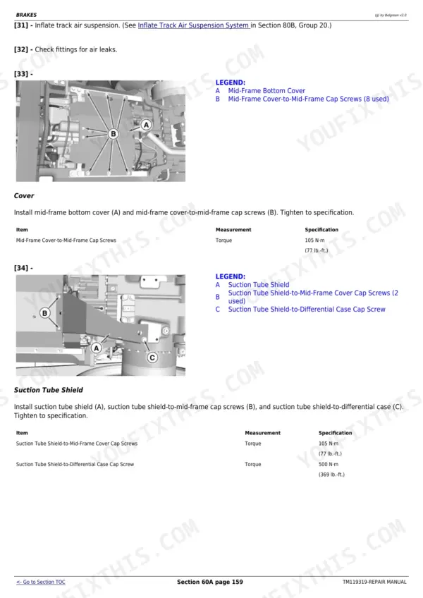
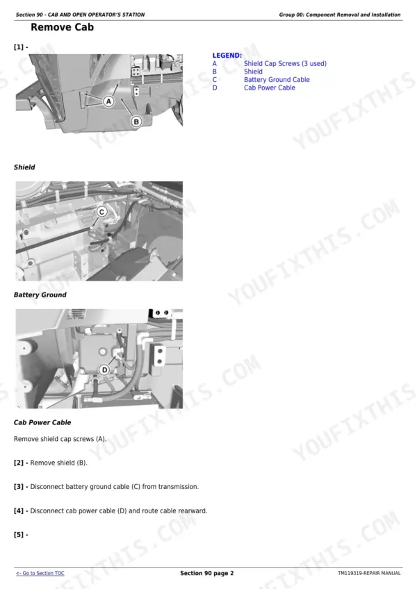
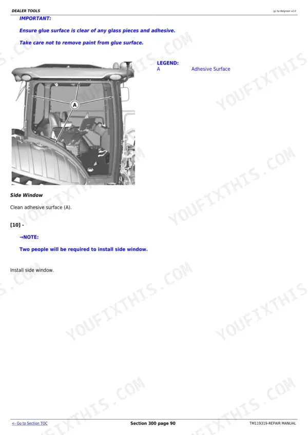
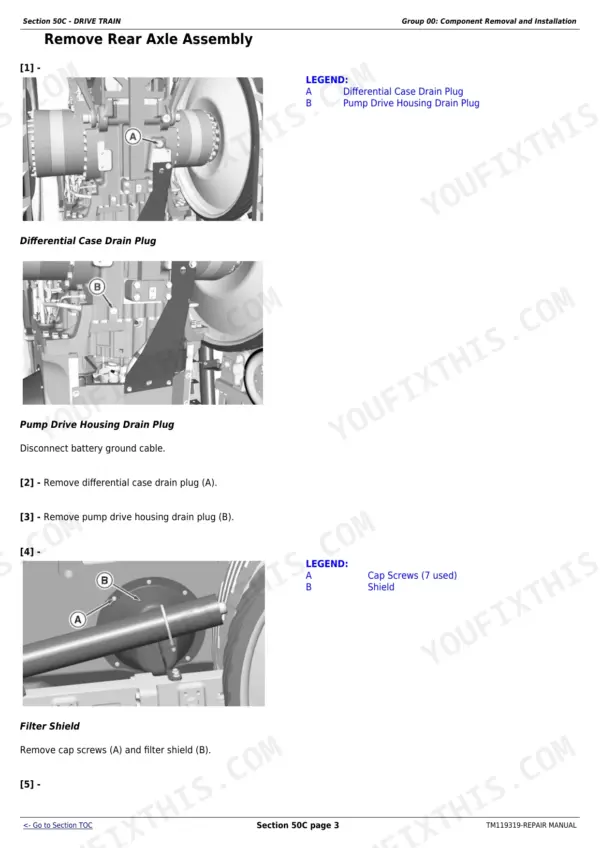
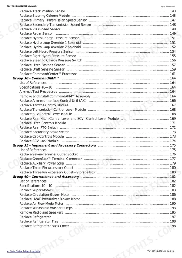
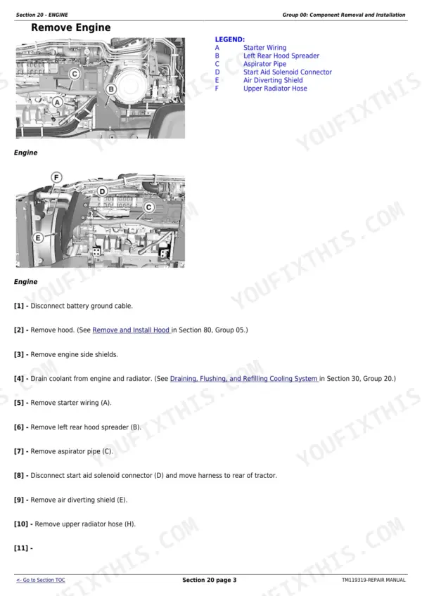
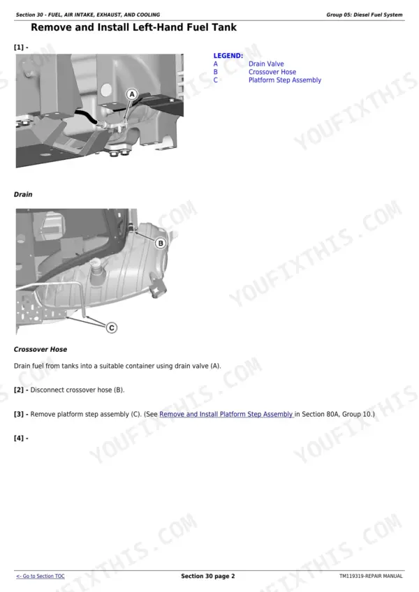
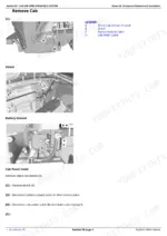
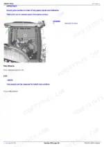
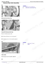
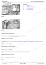
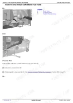
This is the factory repair manual (TM119319) for John Deere 8320RT, 8345RT, and 8370RT track tractors - 1,468 pages of removal, installation, and repair procedures with letter-callout photo illustrations on nearly every job. It covers the engine, the IVT and E23 transmissions in depth (nearly 400 pages, including in-tractor repair), final drives, PTO, steering, brakes, hydraulics, and the full track system: track frame, tension cylinder and accumulator, and suspension. You also get cab and HVAC work, the ComfortCommand seat, electrical circuits including the CommandARM, a complete torque and sealant reference, and a dealer-fabricated tools section. This is the repair book, not the diagnostic manual - it tells you how to take it apart and put it back right.
Other edition of this manual
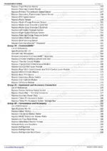
What's Inside This John Deere 8320RT to 8370RT Repair Manual
| System | Pages | Key Topics |
|---|---|---|
| General Information | 9-75 | Safety, General Reference, Torque Values, Sealants and Adhesives, Trademarks |
| Engine | 76-100 | Component Removal and Installation, Engine Repair |
| Fuel, Air Intake, Exhaust, and Cooling | 101-272 | Diesel Fuel System, Air Intake, Auxiliary Drive, Radiator and Coolers, Exhaust System |
| Electrical | 273-474 | Connectors, Charging Circuit, Starting Circuit, Relays/Fuses/Solenoids/Switches, Monitoring System, CommandARM |
| Transmission | 475-856 | Infinitely Variable Transmission (IVT), E23 Transmission, Component Removal, In-Tractor Repair, Assembly |
| Drive Train | 857-1016 | Rear Axle Assembly, Steering Gears, Final Drives, PTO, Mid-Frame Drive Shafts |
| Brakes | 1017-1064 | Service Brakes, Hydraulic Trailer Brakes |
| Steering | 1065-1119 | Steering Column, Steering Valves, Steering Pump, Steering Motor |
| Hydraulics | 1120-1218 | Component Removal, Hydraulic System, Integrated Hydraulic Pump, Hitch Valve, Selective Control Valves, Rear Hitch |
| Miscellaneous | 1219-1239 | Hood and Side Panels, Platform Step Assembly |
| Track Frame and Components | 1240-1348 | Track, Tension Cylinder and Accumulator, Track Frame, Track Suspension |
| Cab and Open Operator's Station | 1349-1439 | Component Removal, HVAC, ComfortCommand Seat, Cab Door and Windshield |
| Dealer Tools | 1440-1468 | Dealer-Fabricated Tools |
Quick Reference Specifications
| Specification | Value | Page |
|---|---|---|
| Metric Bolt Torque (M6 Class 4.8) | 4.7 N.m (42 lb.-in.) | p. 45 |
| Metric Bolt Torque (M36 Class 12.9) | 4750 N.m (3500 lb.-ft.) | p. 45 |
| Unified Inch Bolt Torque (1/4 SAE Grade 1) | 3.7 N.m (33 lb.-in.) | p. 46 |
| Unified Inch Bolt Torque (1-1/2 SAE Grade 8) | 4550 N.m (3350 lb.-ft.) | p. 46 |
| Standard Pressure Face Seal Torque (Dash -4) | 25 N.m (18 lb.-ft.) | p. 49 |
| High Pressure Face Seal Torque (Dash -4) | 35 N.m (26 lb.-ft.) | p. 50 |
| Track Position Sensor Bracket Retaining Cap Screw Torque | 35 N.m (26 lb.-ft.) | p. 415 |
John Deere 8320RT to 8370RT Common Problems This Manual Covers
Weak or lost hydraulic function from pump wear, internal leakage, or air in the system
The Hydraulics section (pages 1120 to 1218) gives removal and repair procedures for the integrated hydraulic pump, hitch valve, and selective control valves, so once you have isolated the leaking or worn component you can pull it, reseal or replace it, and set it back up correctly.
Manual Section: Hydraulics p. 1120Hard starting or no-start traced to the electrical side
The Electrical section (pages 273 to 474) covers the starting and charging circuits, connectors, relays, fuses, and switches. Worth knowing from the starting circuit group on page 352: the master fuse does not protect the starter motor, so check that circuit separately before condemning parts.
Manual Section: Electrical p. 352One track side running hot or dragging from tension imbalance, bearing wear, or final drive friction
Split the job between two sections: Track Frame and Components (pages 1240 to 1348) for the track, tension cylinder, accumulator, and suspension, and Drive Train (pages 857 to 1016) for final drives and the rear axle assembly where a worn bearing usually hides.
Manual Section: Track Frame and Components p. 1240Transmission debris contamination after an IVT failure
The Transmission section covers IVT contamination cleanup starting at page 504: flushing the differential housing and cleaning the oil reservoir before the new or rebuilt unit goes in. Skipping this step is how a second transmission dies early, and the book does not let you skip it.
Manual Section: Transmission p. 504Frequently Asked Questions
Does this manual cover the IVT transmission teardown, or just external service?
Full teardown. The Transmission section runs from page 475 to 856 and covers both the IVT and E23: component removal, in-tractor repair, and complete assembly procedures. It even covers contamination cleanup after a failure - page 504 walks through flushing the differential housing and cleaning the oil reservoir so debris does not kill the replacement unit. p. 504
I have weak or dead hydraulics. Will this manual help me fix it?
It will help you repair what you find, yes. The Hydraulics section (pages 1120 to 1218) covers component removal, the integrated hydraulic pump, hitch valve, selective control valves, and rear hitch. Common causes like pump wear, internal leakage, and filter issues all end in a repair job this book documents step by step. For pinpointing which component is at fault, Deere puts fault diagnosis in a separate Diagnostic Technical Manual - this one is the fix-it half. p. 1120
Are wiring diagrams and fault codes included?
No, and I will be straight about it: this is the Repair Manual, so it carries removal and repair procedures with photo illustrations, not wiring schematics or a trouble code list. The manual itself directs fault diagnosis to the separate Diagnostic Technical Manual. What you do get electrically is 200 pages on connectors, charging and starting circuits, relays, fuses, solenoids, switches, and the CommandARM (pages 273 to 474). One useful catch from the starting circuit group: the master fuse does not protect the starter motor. p. 352
Does it cover the track system, or is it just the wheeled 8R book with a different cover?
This is the RT-specific book. There is a dedicated Track Frame and Components section, pages 1240 to 1348, covering the track itself, the tension cylinder and accumulator, the track frame, and the suspension. Track-related torques are in there too - for example, the track position sensor bracket retaining cap screws torque to 35 N·m (26 lb.-ft.), given on page 415. p. 415
Are torque specs and sealant callouts included, or do I have to hunt for them?
The General Information section (pages 9 to 75) has full torque tables, sealant and adhesive references, and safety info. The metric bolt chart on page 45 alone runs from an M6 class 4.8 at 4.7 N·m (42 lb.-in.) up to an M36 class 12.9 at 4750 N·m (3500 lb.-ft.), and pages 49 to 50 cover face seal fitting torques for hydraulic lines. Individual procedures also call out their own specs where it matters. p. 45








Reviews
There are no reviews yet.