Part of the John Deere Repair Manuals.
A 2030 that will not lift the loader can eat an afternoon of guessing, and somewhere in these 360 pages sits the pressure test that ends the argument. TM-1051 is John Deere's own technical manual for the 2030 tractor, serial number 187301 and up, covering both the U.S. and Mannheim built machines.
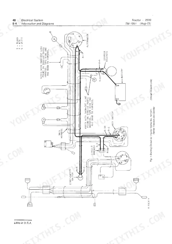
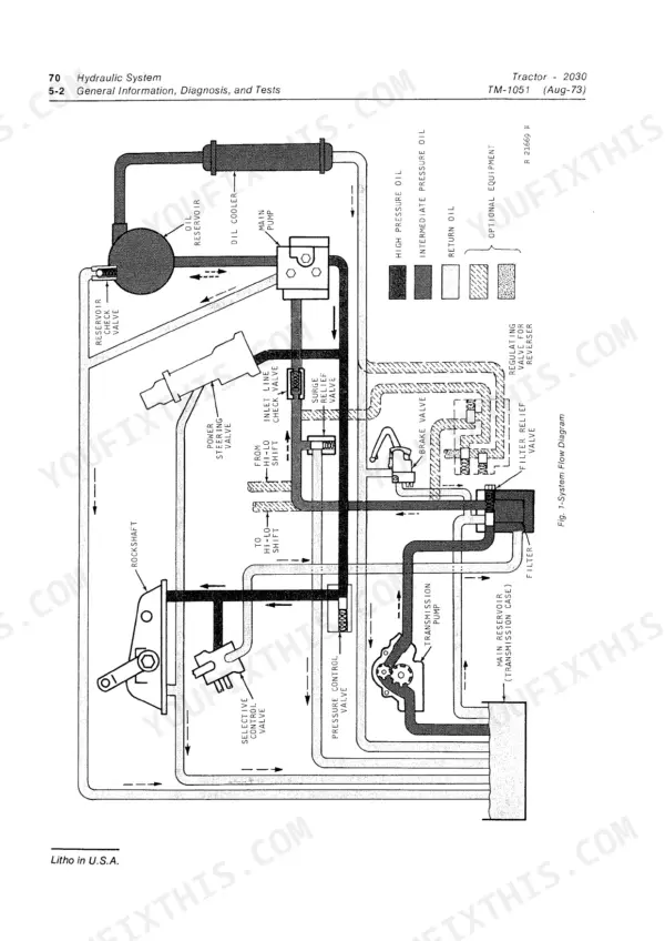
Eight sections run from tune-up and lubrication through the engine, the diesel and gasoline fuel systems, the electrical circuits and wiring diagrams, the power train with its clutches, Hi-Lo shift unit, reverser, collar shift transmission, differential, final drive and PTO, then steering and brakes, the hydraulic system with the rockshaft and selective control valve, and the front axle.
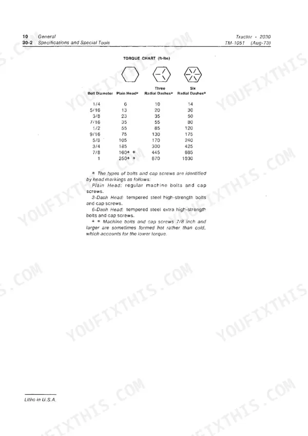
You get torque values, clearances, test pressures, diagnosis charts and step by step teardown and assembly, as a bookmarked PDF download you can keep in the shop or print a page at a time for the bench, so the tractor is back in the field before the weather turns.
What's Inside This John Deere 2030 Manual
| System | Pages | Key Topics |
|---|---|---|
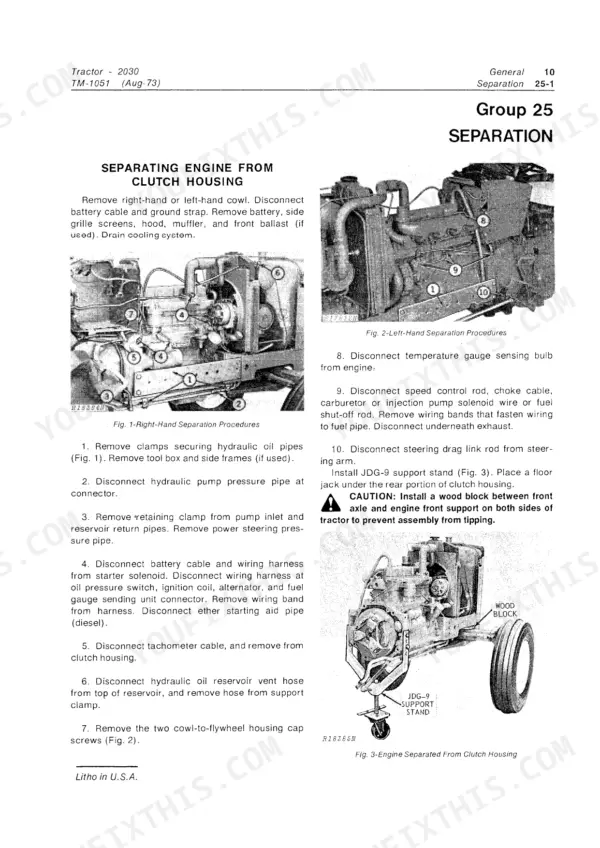
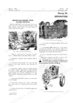
| General | 5-28 | Predelivery, Delivery, And After-Sale Services, Tune-Up and Adjustment, Lubrication, Separation, Specifications and Special Tools |
| Engine | 29-66 | Cylinder Head, Valves, Camshaft and Timing Gear Train, Cylinder Block, Liners, Pistons and Rods, Crankshaft, Main Bearings and Flywheel |
| Fuel System | 67-120 | Diagnosing Malfunctions, Air Intake System, Diesel Fuel System, Gasoline Fuel System, Control Linkage, Tank, Transfer Pump, Filter and Air Cleaner |
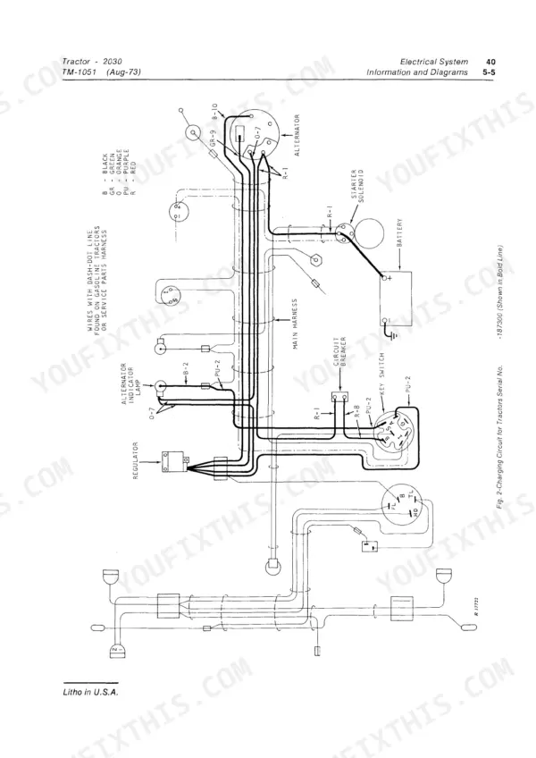
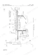
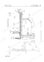
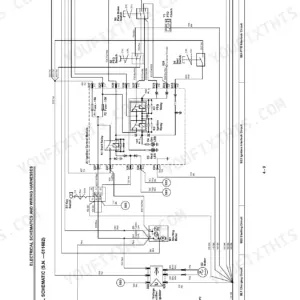
| Electrical System | 121-186 | Information and Diagrams, Charging Circuit, Starting Circuit, Ignition Circuit, Lighting and Accessory Circuits, Diagnosing Malfunctions, Components and Wiring Diagram |
| Power Train | 187-286 | Clutches, Transmission Clutch and Clutch Linkage, Hi-Lo Shift Unit, Reverser, Collar Shift Transmission, Differential, Final Drive, Continuous and Transmission PTO |
| Steering and Brakes | 287-288 | Steering Valve, Steering Piston, Brake Valve, Brake Piston, Brake Disk, Brake Pressure Plate |
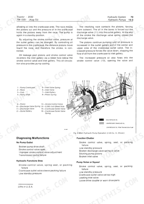
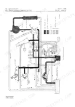
| Hydraulic System | 289-350 | Miscellaneous Hydraulic Components, Hydraulic Pumps, Steering System, Hydraulic Brakes, Rockshaft System, Selective Control Valve, Breakaway Couplers, And Remote Cylinders |
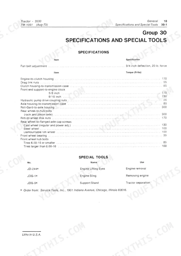
| Miscellaneous | 351-360 | Front Axle, Specifications and Special Tools |
Quick Reference Specifications
| Specification | Value | Page |
|---|---|---|
| Brake Disk minimum groove depth | 0.006 in. | p. 281 |
| Clutch release lever adjusted height variation | 0.010 inch | p. 191 |
| Hydraulic System Standby oil pressure | 2250 psi | p. 6 |
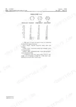
| Water pump cover cap screws torque | 35 ft-lbs | p. 65 |
| Pulley-to-hub cap-screws torque | 21 to 25 ft-lbs | p. 57 |
| Impeller fins to pump housing clearance | within 0.010 inch | p. 57 |
| Governor drive shaft O.D. at thrust bearing | 0.436 to 0.438 inch | p. 59 |
| Compressive load (No PTO) | 158 to 175 lbs | p. 190 |
| Reverser forward clutch disk groove depth | 0.010 to 0.020 in. | p. 282 |
| Oil filter relief valve spring free length | 2-9/16 inches | p. 293 |
| Oil filter relief valve spring compressed length | 1-5/16 inches at 9-1/2 to 10-1/2 lbs. pressure | p. 293 |
| Inlet line check valve spring free length | 1/2 inch | p. 294 |