Part of the John Deere Repair Manuals.
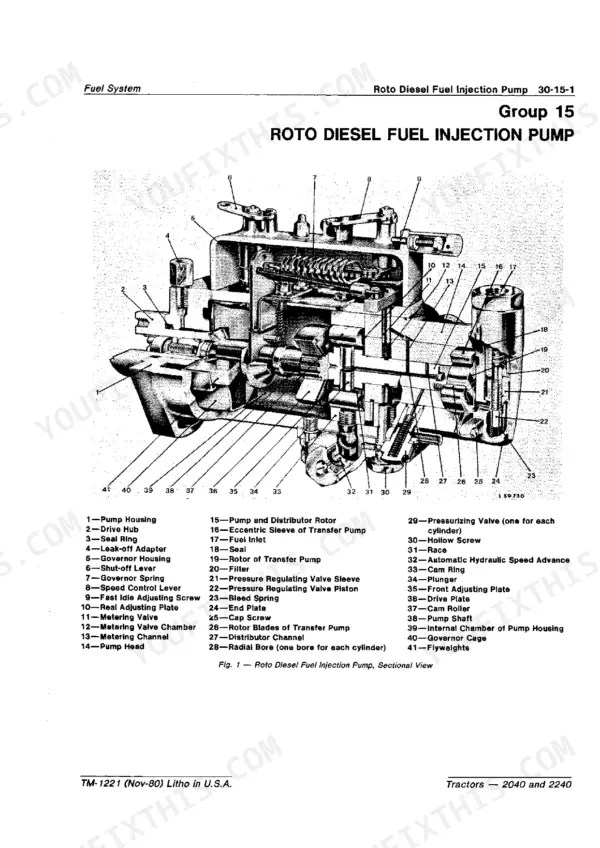
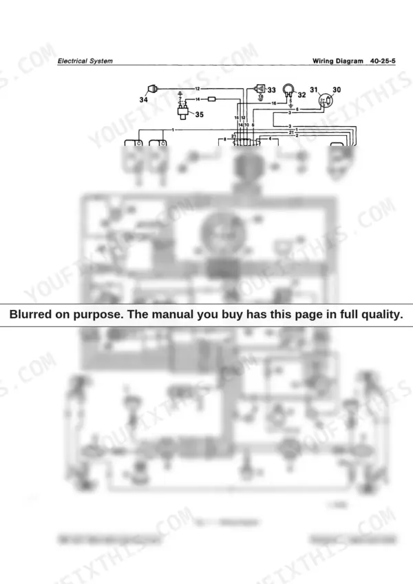
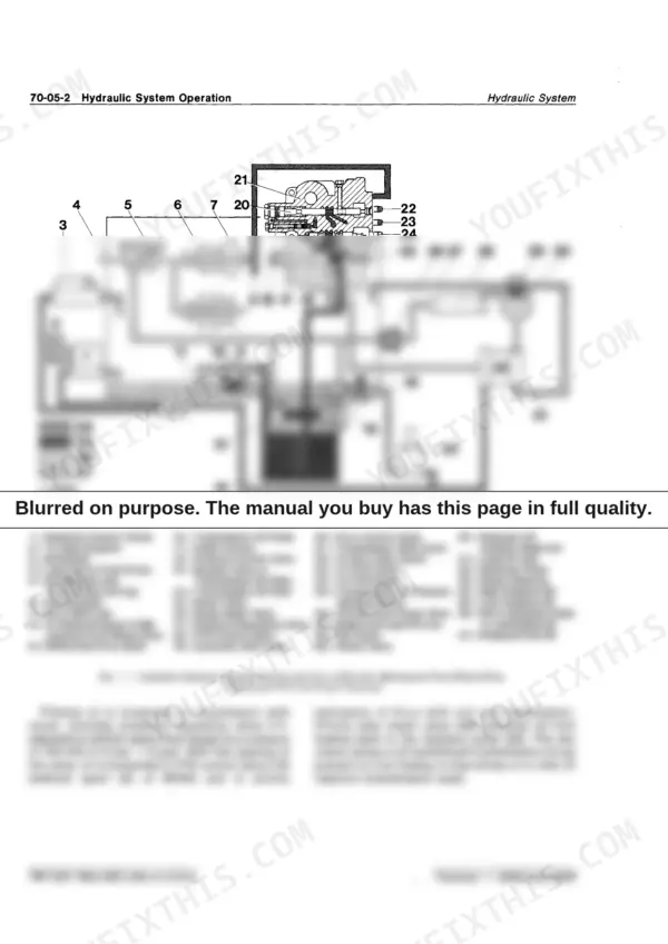
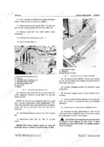
TM1221 is the 586-page John Deere 2040, 2240 Technical Manual PDF (Serial No. 350,000-up) that Deere wrote for its own service departments, covering the Roto Diesel fuel injection pump, the rockshaft, and every other system end to end. Factory wiring diagrams trace every harness from the alternator through the lighting circuits, and the hydraulic section walks through system tests on the pump, rockshaft, and selective control valves before you ever split a housing. Power train coverage runs from the Hi-Lo shift unit and reverser transmission through the differential, final drives, and independent PTO. Set up the 2-post ROLL-GARD with crossbar cap screws and U-bolt nuts torqued to 230 N·m (170 ft-lbs), torque front wheel rim-to-hub bolts to 180 N·m (130 ft-lbs) on tractors without MFWD, and hold clutch pedal free travel at roughly 25 mm. Guess on a clutch adjustment and the price is a second split. Bookmarked and text-searchable, this download puts the right torque and clearance figures in front of you instead of a forum guess.
Other editions of this manual
What's Inside This Manual
| System | Pages | Key Topics |
|---|---|---|
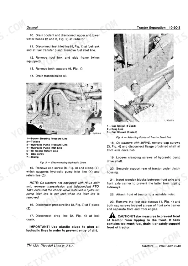
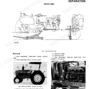
| General | 3-66 | Pre-Delivery, Delivery and After-Sales Inspections, Lubrication and Periodic Service, Engine and Tractor Tune-Up, Tractor Separation |
| Engine | 67-128 | Cylinder Head and Camshaft, Cylinder Block, Liners, Pistons and Connecting Rods, Crankshaft, Main Bearings and Flywheel, Timing Gear Train, Engine Lubrication System |
| Fuel System | 129-164 | Diagnosing Malfunctions, Fuel Tank, Fuel Transfer Pump and Fuel Filter, Roto Diesel Fuel Injection Pump, Fuel Injection Nozzles, Ether Starting Aid, Speed Control Linkage |
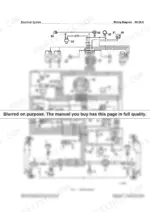
| Electrical System | 165-220 | Description and Diagnosing Malfunctions, Wiring Harnesses, Controls and Instruments, Lighting Systems, Wiring Diagram, Starting Motor, Alternator |
| Power Train | 221-416 | Engine Clutches and Clutch Linkages, Hi-Lo Shift Unit, Reverser Transmission, Synchronized Transmission and Transmission Oil Pump, Collar Shift Transmission and Transmission Oil Pump, Differential, Final Drives, Independent PTO, Continuous Running PTO, Mechanical Front Wheel Drive |
| Steering System and Brakes | 417-444 | Power Steering, Brakes |
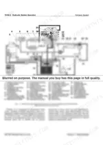
| Hydraulic System | 445-560 | Hydraulic System Operation, Hydraulic System Tests, Oil Reservoir, Filter, Valves and Oil Cooler, Hydraulic Pump, Rockshaft, Selective Control Valves and Breakaway Coupler |
| Miscellaneous | 561-586 | Specifications, Front Axle, Belt Pulley, Front and Rear Wheels, Roll-Gard Protective Structure, Operator's Station |
Every system also includes specifications and special tools.
Quick Reference Specifications
| Specification | Value | Page |
|---|---|---|
| Engine Firing Order | 1-2-3 | p. 7 |
| Engine Intake Valve Clearance | 0.35 mm (0.014 in.) | p. 7 |
| Engine Exhaust Valve Clearance | 0.45 mm (0.018 in.) | p. 7 |
| Maximum Torque | 2040: 152 N·m (112 ft-lbs) · 2240: 185 N·m (136 ft-lbs) | p. 7 |
| Fuel Tank Capacity | 78 L (20.6 U.S. gal.) | p. 11 |
| Engine Crankcase Oil Capacity (with filter) | 7 L (1.8 U.S. gal.) | p. 11 |
| Hydraulic System Operating Pressure | 14000 kPa (140 bar, 2050 psi) | p. 11 |
| Oil Cooler Capacity | 2 L (0.5 U.S. gal.) | p. 12 |
| Clutch Pedal Free Travel | approx. 25 mm (1 in.) | p. 13 |
| Start Safety Switch Torque | 50 N·m (35 ft-lbs) | p. 13 |
| Front Wheel Toe-In | 3 to 6 mm (0.12 to 0.25 in.) without MFWD · 0 to 3 mm (0 to 0.12 in.) with MFWD | p. 13 |
| 2-Post Roll-Gard Attaching Hardware (Crossbar Cap Screws & U-Bolt Nuts) | 230 N·m (170 ft-lbs) | p. 13 |
| Engine Oil Change Interval | 100 hours | p. 14 |
| Thickness of New Clutch Disk (Single-Stage, Independent PTO) | 10 mm (0.39 in.) | p. 226 |
| Clearance Between Special Washer and Operating Sleeve in Valve Housing Assembly | 0.03 to 0.07 mm (0.0012 to 0.0027 in.) | p. 419 |
| Hydraulic Pump Delivery per Shaft Revolution | 22.6 cm³ (1.38 cu.in.) | p. 447 |
| Minimum Pump Delivery at 2000 rpm / 14000 kPa (140 bar, 2050 psi) | 34 L/min. (9.0 gpm) | p. 447 |
| Selective Control Valve Component O.D.s | 12.60 to 12.62 mm (0.496 to 0.497 in.) pressure/return valves · 19.00 to 19.02 mm (0.748 to 0.749 in.) flow control valve | p. 453 |
| Pressure Control Valve Spring Free Length | 117 mm (4.62 in.) | p. 509 |
| Remote Cylinder Piston Diameter | 76 mm (3 in.) | p. 557 |