
Part of the John Deere Repair Manuals.
When the Hi-Lo unit starts slipping mid shift or the rockshaft drifts under a loaded planter, the John Deere 2440, 2640 technical manual PDF answers with 608 pages of factory publication TM1219, Deere's full repair and test book for both tractors. Wiring diagrams trace the charging, starting, and lighting circuits wire by wire, and hydraulic system tests run the pumps, selective control valve, and remote couplers through pressure diagnosis before you pull anything apart. Engine, power train, steering, and brake repair each get their own teardown sections. Torque the front axle cap screws to 406 N·m (300 ft-lbs) and set fan belt deflection at 19 mm before you chase a charging fault. A split tractor waits while you hunt one spec. Print what you need; these pages can take grease on the bench while the bookmarked, keyword-ready file stays clean.
What's Inside This John Deere 2440, 2640 Manual
| System | Pages | Key Topics |
|---|---|---|
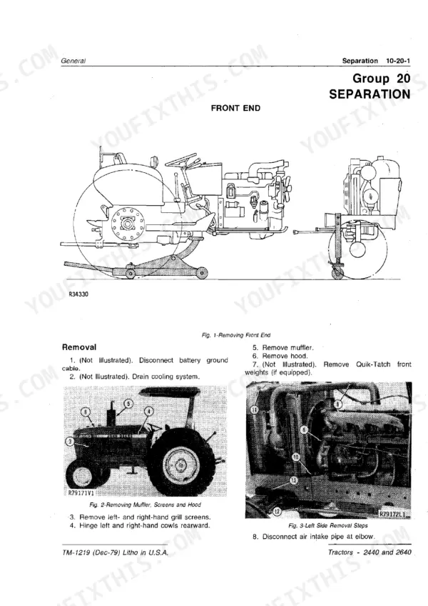
| General | 5-60 | Specifications, Predelivery, Delivery and After-Sale Services, Tune-Up, Lubrication, Separation, Special Tools |
| Engine Repair | 61-124 | Cylinder Head, Valves, Camshaft and Timing Gear Train, Cylinder Block, Liners, Pistons and Rods, Crankshaft, Main Bearings and Flywheel |
| Fuel and Air Repair | 125-160 | Air Intake System, Diesel Fuel System, Control Linkage |
| Electrical Repair | 161-206 | Charging Circuit, Starting Circuit, Lighting and Accessory Circuits |
| Power Train Repair | 207-290 | Clutches, Hi-Lo Shift Unit, Reverser |
| Steering/Brakes Repair | 291-316 | Steering, Brakes, Auxiliary Brake |
| Hydraulic Repair | 317-398 | Miscellaneous Hydraulic Components, Hydraulic Pumps, Rockshaft and Implement Hitches |
| Miscellaneous Repair | 399-400 | Cowl Assembly |
| Engine Operation and Tests | 401-412 | System Tests and Diagnosis |
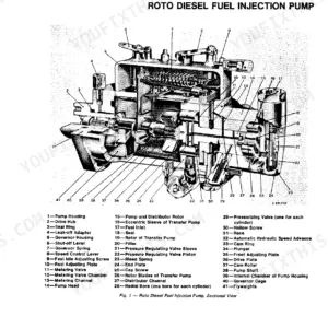
| Fuel/Air Operation and Tests | 413-440 | Air Intake System (Air Cleaner, Restriction Indicator, Testing Switch Operation, Ether Starting Aid), Diesel Fuel System (Fuel Supply Pump, Fuel Filter, Bleeding the Fuel System, Fuel Injection Pump), Fuel Injection Nozzles (How the Nozzle Works, Diagnosing Malfunctions), Control Linkage (Hand Throttle, Foot Throttle, Adjustments), Specifications and Special Tools |
| Electrical Operation and Tests | 441-496 | General Information and Diagrams, Charging Circuit Diagnosis, Starting Circuit Diagnosis |
| Power Train Operation and Tests | 497-526 | Clutch and Transmission Operation, Hi-Lo Shift Unit Operation, Reverser Operation |
| Steering/Brakes Operation and Tests | 527-538 | Power Steering, Hydraulic Brakes, Auxiliary Brake |
| Hydraulic Operation and Tests | 539-608 | Hydraulic System Operation, Hydraulic System Tests, Selective Control Valve, Couplers and Remote Cylinders |
Quick Reference Specifications
| Specification | Value | Page |
|---|---|---|
| All Models | ||
| Front axle cap screws | 406 N·m (300 ft-lbs) | p. 9 |
| Front rim to hub cap screws | 136 N·m (100 ft-lbs) | p. 9 |
| Slow Idle | 800 rpm | p. 30 |
| Fast Idle (no load) | 2650 rpm | p. 30 |
| Fan belt deflection | 19 mm (3/4 in.) | p. 30 |
| Fan belt tension force | 90 N (20 lb.) | p. 30 |
| Brake Disk (with Hi-Lo) Thickness | 5.9 to 6.1 mm (0.23 to 0.24 in.) | p. 214 |
| Brake Band (without Hi-Lo) Thickness | 2.16 to 2.41 mm (0.085 to 0.095 in.) | p. 214 |
| Shaft end play (22.6 cm³ pump) | 0.74-1.75 mm (0.029-0.069 in.) | p. 319 |
| Shaft end play (39.3 cm³ pump) | 0.02-0.08 mm (0.001-0.003 in.) | p. 319 |
| 2440 | ||
| Engine Horsepower (2440) | 45.3 kW (60.7 hp) | p. 5 |
| 2640 | ||
| Engine Horsepower (2640) | 52.5 kW (70.4 hp) | p. 5 |
John Deere 2440, 2640 Common Problems This Manual Covers
John Deere 2440 or 2640 hydraulics, steering, and three point hitch all dead at once
Check transmission oil level and pull the hydraulic filter first; brake material plugs the pickup screen on these tractors. Trace the circuit with the hydraulic schematic. If the front pump is suspect, measure shaft end play with a dial indicator against the spec for your pump on page 319 — the 22.6 cm3 (1.38 cu-in) main pump allows 0.74 to 1.75 mm (0.029 to 0.069 in.) — before condemning it.
Manual Section: Hydraulic Operation and Tests p. 319Hydraulic pump chatters and oil runs hot after an hour of loader work
Drain and inspect the pickup screen and filter for brake lining debris before touching the pump. Fill to the correct level and retest under load. If chatter continues, pull the inlet valves and install new assemblies, torquing the inlet valve plugs on page 342 to 136 N·m (100 ft-lbs).
Manual Section: Hydraulic Repair p. 342Transmission grabs two gears at once or sticks in gear after a sloppy shift
Remove the shift cover and inspect the shift rails and detents for wear or misalignment; work the levers slowly through each gate before splitting anything. Review transmission operation starting on page 497 to confirm rail travel. On reassembly, torque the clutch housing to transmission cap screws to 115 N·m (85 ft-lbs).
Manual Section: Power Train Repair p. 213PTO clutch slips under load, baler slows down while the engine holds rpm
Measure PTO clutch disk thickness after splitting the tractor. With a Hi-Lo unit, replace disks worn below the 2.44 to 2.54 mm (0.096 to 0.100 in.) spec on page 281; without Hi-Lo, compare against 0.84 to 0.94 mm (0.033 to 0.037 in.) on page 284. Replace the PTO seal while the housing is open.
Manual Section: Power Train Repair p. 281Three point hitch settles under load or rockshaft rises slowly with a mounted plow
Check rockshaft valve adjustment and inspect the cylinder for internal leakage before blaming the pump. Test with a known good implement on the hitch. If you pull the cylinder and valve housing, renew the seals and torque the housing cap screws to 58 N·m (43 ft-lbs) as listed on page 320.
Manual Section: Hydraulic Repair p. 320Engine cranks slowly on cold mornings or the starter solenoid just clicks
Test battery specific gravity first; it should read 1.260 at 27°C (80°F) per page 9. Clean and tighten both battery cables and the ground strap, then load test the battery. If cranking is still slow, run the starting circuit checks in the electrical tests section beginning on page 441.
Manual Section: Electrical Operation and Tests p. 441Frequently Asked Questions
What is the torque specification for the cylinder head bolts on a 2440 or 2640 tractor?
The cylinder head cap screws for the 2440 and 2640 tractors must be torqued to 129 N-m (95 ft-lbs). This procedure is detailed in the Engine Repair section. p. 82
What is the torque specification for the front wheel cap screws on a 2640 tractor?
The front wheel cap screws for the 2640 tractor should be torqued to 136 N-m (100 ft-lbs). p. 17
What is the service interval for replacing the transmission/hydraulic oil filter on a John Deere 2440 or 2640 Tractor?
The transmission/hydraulic system oil filter should be replaced every 600 hours of operation. p. 44
What is the correct fan belt tension for the 2440 and 2640 tractors?
The fan belt should be adjusted to have a deflection of 19 mm (3/4 in.) when 90 N (20 lb.) of force is applied midway between the pulleys. p. 8
What is the engine oil capacity for the 2440 and 2640 tractors including the filter?
The 2440 tractor has an engine crankcase oil capacity of 5.7 L (6 U.S. quarts), while the 2640 tractor has a capacity of 8.6 L (9 U.S. quarts). p. 44
Do I get instant access to this John Deere 2440 Technical Manual?
One searchable PDF covering 608 pages, delivered instantly. No disc, no shipping, no waiting on the post.
Am I able to print pages from this John Deere 2440 manual?
Yes. Print the sections you need to take out to the shop for your own use. Standard letter or A4 paper works.









Reviews
There are no reviews yet.