![John Deere 7715, 7815 Repair Manual [Tractors]](https://youfixthis.com/wp-content/uploads/2012/02/Manual_Download-300x300.jpg)
Part of the John Deere Repair Manuals.
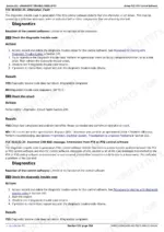
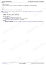
This is the factory diagnostic manual (TM-series) for the 2013-2021 John Deere 6M tractors: 6105M, 6115M, 6125M, 6130M, 6140M, 6150M and 6170M in one book. It is the fault-finding half of the documentation - full DTC tables for all seven models, symptom-based diagnosis for no-code problems, functional and diagnostic wiring schematics, ECU pin-outs, connector views and harness routing. Hydraulic and transmission sections carry real test values: PC low-pressure circuit max 1750 kPa, PFC 2300 kPa, high-pressure circuit 21000 kPa, SCV operational checks at 40 degrees C oil temperature. PowrQuad, PowrReverser and SyncroPlus are all covered. These are Final Tier 4 machines with DPF and CAN bus, so this book earns its keep fast.
Complete the set for your 6105M-6170M
What's Inside This John Deere 6105M-6170M Manual
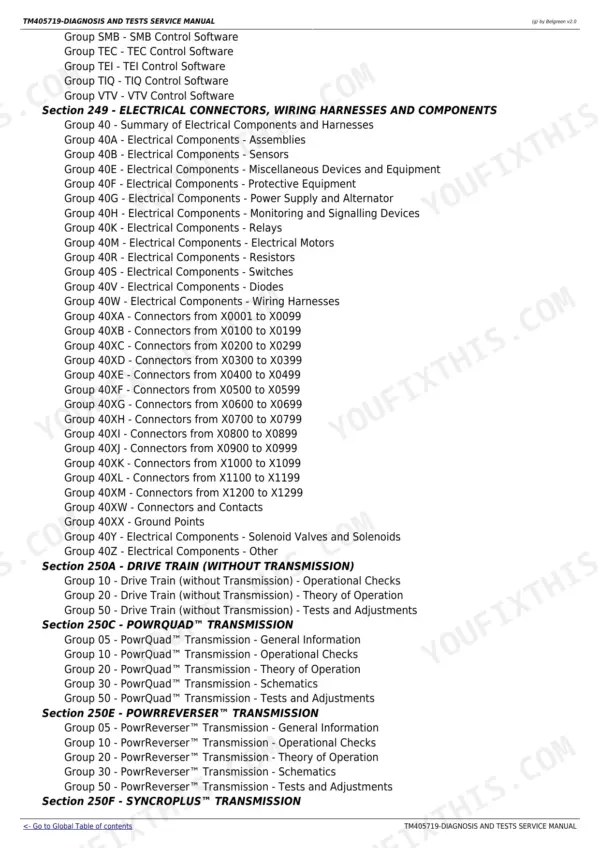
| System | Pages | Key Topics |
|---|---|---|
| General Information | 12-105 | Diagnostic Approach, How to Read Schematics, Reference Information |
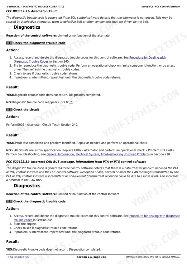
| Diagnostic Trouble Codes (Dtc) | 106-857 | Fault Code Tables for All 7 Models, Dtc Diagnostics, Code-To-Repair Procedures |
| Observable Symptoms and System Diagnosis | 858-898 | Symptom-Based Troubleshooting, No-Code Faults |
| Engine | 899-909 | Engine Diagnosis, Performance Tests |
| Fuel, Air Intake and Cooling Systems | 910-952 | Fuel System, Air Intake, Cooling, DPF, Component Tests |
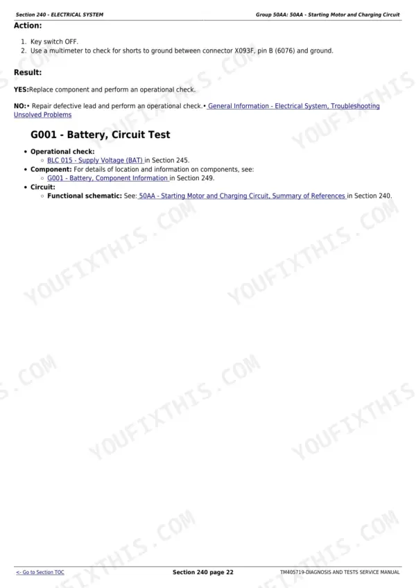
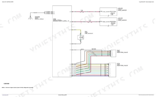
| Electrical System | 953-1735 | Functional & Diagnostic Schematics, Starting & Charging, Circuit Tests, Harness Testing |
| Electronic Control Units | 1736-2220 | ECU Diagnostics, Controller Pin-Outs, Software/calibration |
| Electrical Connectors, Wiring Harnesses and Components | 2221-3493 | Connector Views, Wiring Harness Routing, Pin-Outs, Component Locations |
| Drive Train (Without Transmission) | 3494-3552 | Driveline Diagnosis, MFWD |
| PowrQuad Transmission | 3553-3675 | PowrQuad Theory & Diagnosis, Hydraulic Schematics, Pressure Tests |
| PowrReverser Transmission | 3676-3804 | PowrReverser Theory & Diagnosis |
| SyncroPlus Transmission | 3805-3915 | SyncroPlus Diagnosis, Drive Train Components |
| Steering and Brakes | 3916-4026 | Steering Diagnosis, Brake Tests, Components |
| Hydraulic System | 4027-4267 | Pressure Checks (PC/PFC), SCV Operational Checks, Pump Tests, Hydraulic Components |
| Machine-Specific and Suspension Systems | 4268-4321 | Machine-Specific Systems, Cab/axle Suspension |
| Operator's Cab | 4322-4373 | HVAC, Instrument Cluster, Cab Electronics |
| Special Tools | 4374-4374 | Jd Special Service Tools |
Quick Reference Specifications
| Specification | Value | Page |
|---|---|---|
| All models | ||
| Hydraulic Oil Temperature for Checks | 40 °C (104 °F) | p. 4027 |
| Cylinder Dimensions for SCV Operational Check | 89 x 203 mm (3-1/2 x 8 in.) | |
| Cylinder Extension Time (Flow Control Valve fully counterclockwise, 2000 rpm) | less than 2.5 seconds | |
| PC Hydraulic System Low Pressure Circuit Maximum Oil Pressure | 1750 kPa (17.5 bar; 254 psi) | p. 4027 |
| PC Hydraulic System High Pressure Circuit Maximum Oil Pressure | 21000 kPa (210 bar; 3046 psi) | p. 4027 |
| PFC Hydraulic System Low Pressure Circuit Maximum Oil Pressure | 2300 kPa (23 bar; 334 psi) | p. 4027 |
| PFC Hydraulic System High Pressure Circuit Maximum Oil Pressure | 21000 kPa (210 bar; 3046 psi) | p. 4027 |
| Hydraulic Oil Filter By-pass Valve Opening Pressure | 450 kPa (4.5 bar; 65 psi) | p. 4027 |
| Lube Oil Valve Opening Pressure | 90 kPa (0.9 bar; 13 psi) | p. 4027 |
| Lube Oil Valve Further Opening Pressure | 140 kPa (1.4 bar; 20 psi) | p. 4027 |
| P3 Hydraulic Pump Displacement | 28 cm³ (1.7 cu. in.) | p. 4027 |
| P4 Hydraulic Pump Displacement | 35 cm³ (2.1 cu. in.) | p. 4027 |
| Engine Speed Limit for Oil Withdrawal | 1500 rpm | |
| Hydraulic Pump Outlet Pressure (during cranking/stand-by) | approx. 2600 kPa (26 bar; 377 psi) | p. 4027 |
| Hydraulic System Shut-off Pressure | 20000 kPa (200 bar; 2950 psi) | p. 4027 |
| Draft Sensor Piston Total Travel | 1.8 mm (0.071 in.) | |
| Stepper Motor Pin Diameter | 3 mm | |
| M-SCV System Pressure Passage Oil Pressure (Extend/Retract) | approx. 2500 kPa (25 bar; 363 psi) | p. 4027 |
| B036 - Neutral Start Switch | ||
| Continuity Check of Lead | 0-1 ohms | |
| G002 - Alternator | ||
| Battery Voltage | 11.5 - 12.5 V | |
| Output Voltage | 13.8 - 15.8 V | |
| Lead 5076 | 12 - 14.5 V | |
| K01LCS/01 - Relay for Power Supply to Electronics (ELX1) | ||
| Circuit Voltage | 11.5 V - 14.0 V | |
| K02LCS/02 - Diode for Power Supply to Electronics | ||
| Circuit Resistance | 0-1 ohms | |
| K056 - Battery Cut-Off Relay | ||
| Resistance of Lead | 0-1 ohms | |
John Deere 6105M-6170M Common Problems This Manual Covers
Hard starting or power loss under load on any of the 6M models
Start with the Diagnostic Trouble Codes section to pull and interpret ECU codes, then run the fuel system component tests in Fuel, Air Intake and Cooling Systems. A restricted fuel filter or saturated DPF shows up clearly in these test procedures.
Manual Section: Diagnostic Trouble Codes (DTC) / Fuel, Air Intake and Cooling SystemsTransmission slip or MFWD that will not engage
The PowrQuad Transmission section gives hydraulic schematics and pressure test procedures to confirm whether system pressure is low from a clogged filter or worn pump. MFWD engagement faults are covered under Drive Train (Without Transmission) with driveline diagnosis steps.
Manual Section: PowrQuad Transmission / Drive Train (Without Transmission)Weak or slow SCV and hitch response
The Hydraulic System section spells out the SCV operational check: oil at 40 degrees C, an 89 x 203 mm cylinder, extension under 2.5 seconds at 2000 rpm. Pressure checks for PC and PFC systems then isolate a tired pump from a valve problem.
Manual Section: Hydraulic SystemElectrical gremlins - intermittent codes, dead circuits, charging complaints
Use the diagnostic schematics and circuit tests in the Electrical System section, then trace the physical wire with connector views and harness routing in the Electrical Connectors, Wiring Harnesses and Components section. Charging spec is 13.8-15.8 V output, so faults verify with a meter.
Manual Section: Electrical System / Electrical Connectors, Wiring Harnesses and ComponentsFrequently Asked Questions
My 6130M threw a fuel pressure DTC and loses power under load - will this manual get me to the actual fault?
Yes, that is exactly what it is for. The Diagnostic Trouble Codes section lists the fault code tables for all seven models with code-to-repair procedures, and the Fuel, Air Intake and Cooling Systems section walks the component tests. On these tractors low fuel pressure is very often a clogged filter (RE544394 on 6105M-6140M, RE541925 on 6150M/6170M), and the manual lets you confirm that with a test instead of guessing parts.
Does it cover the DPF? Mine keeps showing a blockage warning.
It does. These are Final Tier 4 engines and the Fuel, Air Intake and Cooling Systems section covers the DPF along with the air intake and cooling side. The DTC section handles the exhaust-related codes so you can tell a saturated filter needing replacement from a sensor or regeneration fault before you spend DPF money. It also helps rule out the cheap cause first - a restricted primary or secondary air filter sets its own warning.
Are the wiring schematics real ones with pin-outs, or just block diagrams?
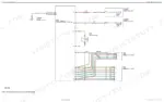
Real ones. The Electrical System section carries both functional and diagnostic schematics plus circuit tests and harness testing, and a separate section gives connector views, wiring harness routing, pin-outs and component locations. Controller pin-outs live in the Electronic Control Units section. With test values like 11.5-12.5 V battery, 13.8-15.8 V charging output and 0-1 ohm continuity spec, you can chase a circuit with a multimeter instead of a parts cannon.
Which transmissions does it cover? I have a PowrQuad but my neighbor's 6115M is a PowrReverser.
All three fitted to the 6M range: PowrQuad, PowrReverser and SyncroPlus each get their own section with theory of operation and diagnosis. The PowrQuad section includes hydraulic schematics and pressure tests, so a slipping range or a soft shift becomes a gauge reading you can compare to spec rather than a shrug.
Is this a repair manual? Will I find overhaul torque specs and disassembly steps?
No - this is the Diagnostic and Tests manual. Its job is finding the fault: codes, symptoms, schematics, pressure and voltage tests with pass/fail values. Teardown procedures and torque specs live in the separate Repair TM. If you diagnose your own machine and want to know exactly which component failed before ordering parts or opening anything up, this is the book you actually use most.