


![John Deere 6105M 6115M 6125M 6130M 6140M 6150M 6170M Diagnostic Technical Manual [Tractors]](https://youfixthis.com/wp-content/uploads/2018/08/2019-06-03_17-01-14-300x300.jpg)
![John Deere 6110J 6125J 6130J Diagnostic Technical Manual [Tractors]](https://youfixthis.com/wp-content/uploads/2012/02/Manual_Download-300x300.jpg)
Part of the John Deere Repair Manuals.
This is the complete John Deere factory Diagnostic and Tests Technical Manual (TM605119) for the 6100D, 6110D, 6115D, 6125D, 6130D and 6140D tractors. Across 1,635 pages it walks you through every diagnostic path on these machines: reading ECU, CCU, Power Reverser and Instrument Cluster trouble codes, running electrical circuit tests with full connector and wiring data, pressure-testing the hydraulic system, and checking the Collar Shift and PowrReverser transmissions, MFWD, brakes, steering and the cab. It is the same reference a John Deere dealer technician uses to pinpoint a fault before touching a wrench - with test pressures, acceptable ranges and test-point locations called out so you confirm the real cause on the first pass.
What's Inside This John Deere 6100D, 6110D, 6115D, 6125D, 6130D, 6140D Manual
| System | Pages | Key Topics |
|---|---|---|
| General | Safety, Tractor Specifications, Serial Number Locations, Diagnostic and Testing Procedures, Operational Checkouts (Electrical, Power Train, Brakes, Hydraulic, Steering) | |
| Diagnostic Trouble Codes | Engine Control Unit (ECU) DTCs, Chassis Control Unit (Ccu) DTCs, Power Reverser Transmission (Ptr) DTCs, Instrument Cluster Controller (Icc) DTCs | |
| Observable Symptoms | Symptom-Based Fault Identification Across All Major Systems | |
| Engine System Diagnosis and Tests | Engine Diagnostics, Test Procedures and Adjustments, Cooling System Diagnosis, Component Information | |
| Fuel and Air Operation and Tests | Air Intake System Diagnostics, Fuel System Diagnosis (4045 Rotary and Hpcr), Test Procedures | |
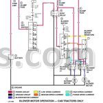
| Electrical System Diagnostics and Tests | Accessing Diagnostic Codes and Addresses, Calibration Procedures, Circuit Code Listing, Connector Information, Component Tests (Ptr, A/C, CAN Bus, Charging, Starting, Lights, PTO, Wiper, Trailer Outlet) | |
| Power Train Diagnosis and Tests | Dry Traction Clutch Diagnostics, Wet Traction Clutch Diagnostics, Power Reverser Diagnostics, Collar Shift Transmission, Top Shaft Synchronized (Tss) Transmission, Component Information | |
| Drive Systems Diagnosis and Tests | MFWD Diagnostics, Power Take-Off (PTO) Diagnostics, Differential and Final Drive Diagnostics | |
| Brake System Diagnosis and Tests | Test Procedures and Adjustments, Brake System Diagnostics, Component Identification | |
| Hydraulic System Diagnosis and Tests | Basic Hydraulic System Diagnostics, Rockshaft System Diagnostics, Rear and Mid Mount SCV Diagnostics, Hydraulic Trailer Brake Valve Diagnostics, Component Information | |
| Steering System Diagnosis and Tests | Test Procedures and Adjustments, Steering System Diagnostics, Component Information | |
| Operator Station Diagnosis and Tests | Air Conditioning and Heating Diagnostics, Seat Diagnostics, Test and Adjustment Procedures, Component Location | |
| Service Tools | Dealer Fabricated Tools, Service Tools and Kits |
Quick Reference Specifications
| Specification | Value | Page |
|---|---|---|
| 6100D, 6110D, 6115D, 6125D, 6130D, 6140D | ||
| Engine Model (all models) | John Deere 4045T (Tier 1) or 4045H (Tier 3/Stage IIIa) PowerTech/PowerTech E | |
| All models | ||
| Engine Displacement | 4.5 L (276 cu in.), 4-cylinder, 106 mm bore x 127 mm stroke | |
| Rated Engine Speed | 2100 rpm | |
| Engine Horsepower (97/68/EC) | 6100D: 72.7 kW (98.9 hp) / 6110D: 79 kW (106 hp) / 6115D: 87 kW (118.4 hp) / 6125D: 91.8 kW (123 hp) / 6130D: 95.4 kW (129.8 hp) / 6140D: 101.3 kW (137.8 hp) | |
| PTO Power (Factory Observed) | 6100D: 61.1 kW (82 hp) / 6110D: 67.1 kW (90 hp) / 6115D: 70.8 kW (95 hp) / 6125D: 78.3 kW (105 hp) / 6130D: 78.3 kW (105 hp) / 6140D: 85.8 kW (115 hp) | |
| Hydraulic Implement Pump Flow at 2100 rpm | 66.62 L/min (17.6 gpm) | |
| Hydraulic System Maximum Pressure | 19,500 kPa (2830 psi) | |
| 3-Point Hitch Lift Capacity at Hitch Point | 3469 kg (7649 lb) | |
| Fuel Tank Capacity | 158 L (41.7 gal) | |
| Engine Oil Capacity (including filter) | 15 L (16 qt) | |
| Coolant System Capacity | 16.5 L (17.4 qt) | |
| Wheelbase | 2350 mm (92.5 in.) | |
| All MFWD-equipped models | ||
| Overall Length (MFWD) | 4216 mm (166 in.) | |
John Deere 6100D, 6110D, 6115D, 6125D, 6130D, 6140D Common Problems This Manual Covers
Intermittent sensor faults or complete controller dropout caused by corroded connectors
Locate the affected connector using the Circuit Code Listing and Connector Information sub-sections in Section 240. Inspect the cavity for bent terminals, moisture ingress or greenish corrosion on the pins. Clean with electrical contact cleaner, apply dielectric grease, and retest the circuit with a voltmeter or breakout box at the terminal specified in the wiring data. Replacing a corroded connector rather than the sensor it serves resolves the majority of recurring fault-code comebacks on these tractors.
Manual Section: Electrical System Diagnostics and TestsSTOP indicator triggered by high hydraulic oil temperature during extended operation in hot weather
Work through the hydraulic temperature diagnosis in Section 270 before assuming a faulty sensor. Check the hydraulic oil level, inspect the oil cooler for debris blocking airflow, and verify the hydraulic filter is within its service interval. If the oil and cooler are good, the manual's test procedure isolates whether the temperature sensor itself is drifting by comparing its reading to a calibrated gauge at the test port.
Manual Section: Hydraulic System Diagnosis and TestsPowrReverser transmission hesitates or slips during directional changes on 6110D and 6130D models
Start with Section 250's PTR diagnostic tree: read any stored PTR codes from Section 211, then perform the clutch engagement pressure test at the test port identified in the Component Information group. A low clutch pressure reading points to the control solenoid or the pressure regulating valve; a normal pressure reading with slip points to the wet clutch pack friction material. The test sequence prevents unnecessary disassembly by ruling out the hydraulic supply circuit first.
Manual Section: Power Train Diagnosis and TestsEngine oil pressure warning triggers at operating temperature on a 6100D or 6115D
Section 220 steps you through the oil pressure test procedure: install a calibrated mechanical gauge at the sender port and compare the actual pressure to the specification at idle and rated speed. If mechanical pressure is within spec, replace the pressure sender (it is a common false-alarm part on the 4045 engine family at high hours). If mechanical pressure is low, the manual directs you to inspect the oil pump, pickup screen and main bearing clearances in sequence before condemning the pump.
Manual Section: Engine System Diagnosis and TestsFrequently Asked Questions
How do I read and clear diagnostic trouble codes on a John Deere 6100D or 6130D?
This manual's Section 240 (Electrical System Diagnostics) walks you step by step through accessing DTCs via the Instrument Cluster, reading the code addresses for the ECU, CCU, PTR and ICC controllers, and clearing codes once the fault is resolved. Section 211 contains the full DTC lookup tables for each controller so you can match the code to the specific circuit or sensor that triggered it.
What does it mean when the STOP indicator lights and the tractor shuts down on a 6115D or 6125D?
A STOP indicator in these tractors usually means the ECU detected a condition requiring immediate shutdown - most often low engine oil pressure or high hydraulic oil temperature. The manual covers the oil pressure circuit test procedure in Section 220 (Engine Diagnostics) and the hydraulic temperature test in Section 270 (Hydraulic System Diagnosis), so you can confirm whether the sensor, the oil pump or the actual oil level is the root cause before replacing parts.
How do I diagnose hydraulic system problems such as weak rockshaft lift or slow SCV response on a 6140D?
Section 270 covers the full hydraulic diagnosis sequence: checking implement pump flow (spec is 66.62 L/min at 2100 rpm), verifying system maximum pressure (19,500 kPa / 2830 psi), and stepping through the Rockshaft and SCV sub-diagnostic trees. The manual tells you the correct test fittings and acceptable pressure ranges at each test point so you can isolate whether the pump, relief valve or the valve block itself is the cause.
Does this manual cover PowrReverser transmission faults on the 6110D and 6130D?
Yes. Section 250 (Power Train Diagnosis) covers both the dry-clutch and wet-clutch variants plus the full PowrReverser diagnostic tree, including reading PTR trouble codes through Section 211. The tests identify whether a shift hesitation or clutch slip traces to a solenoid, a pressure sensor, or the wet clutch pack itself before any disassembly.
How do I diagnose electrical problems such as intermittent sensor faults or corroded connectors on a 6125D?
Section 240 is the most detailed electrical section in the manual - it covers every major circuit on these tractors, from the CAN bus to the starting system, with connector pinouts, circuit code listings and component locations. The connector identification sub-section (Group 20B) is the starting point for any intermittent fault: it shows you the exact connector number, cavity assignment and wire color so you can scope the signal at the right pin rather than chasing the harness.
What do I get after purchasing this John Deere 6100D, 6110D, 6115D, 6125D?
A 1635-page Diagnostic in searchable PDF format (57 MB), available the moment you complete checkout. View on computer, tablet, or phone, with no shipping wait.
Are there any print restrictions on this John Deere 6100D, 6110D, 6115D?
Zero restrictions. The PDF is DRM-free. Print whatever sections you need to take out to the shop. Standard letter or A4 paper works.


Reviews
There are no reviews yet.