


Part of the John Deere Repair Manuals.
This is the complete John Deere factory repair manual (TM1575) for the 8100, 8200, 8300, 8400, 8110, 8210, 8310 and 8410 row-crop tractors. Across 1,124 pages it covers every major system on both the 8000 Series and the 8000 TEN Series machines: removing and rebuilding the 7.6L and 8.1L diesel engines, servicing the Power Shift Transmission specific to each model generation, repairing the front and rear drive systems and MFWD axles, tracing the full electrical harness with wiring diagrams, and working through the hydraulic pumps, selective control valves and hitch. It is the same information a John Deere dealer technician works from, with torque values, test pressures and fluid capacities called out so each repair is done to spec the first time.
What's Inside This John Deere 8100, 8200, 8300, 8400, 8110, 8210, 8310, 8410 Repair Manual
| System | Pages | Key Topics |
|---|---|---|
| Dealer Predelivery Service | Pre-Delivery Inspection, Initial Adjustments, Lubrication and Fluid Level Checks | |
| General Information | Safety, Specifications | |
| Engine | Component Removal and Installation, Engine Repair | |
| Fuel and Cooling Systems | Diesel Fuel System, Air Intake System, Engine Cooling System, Air Conditioning Condenser and Coolers | |
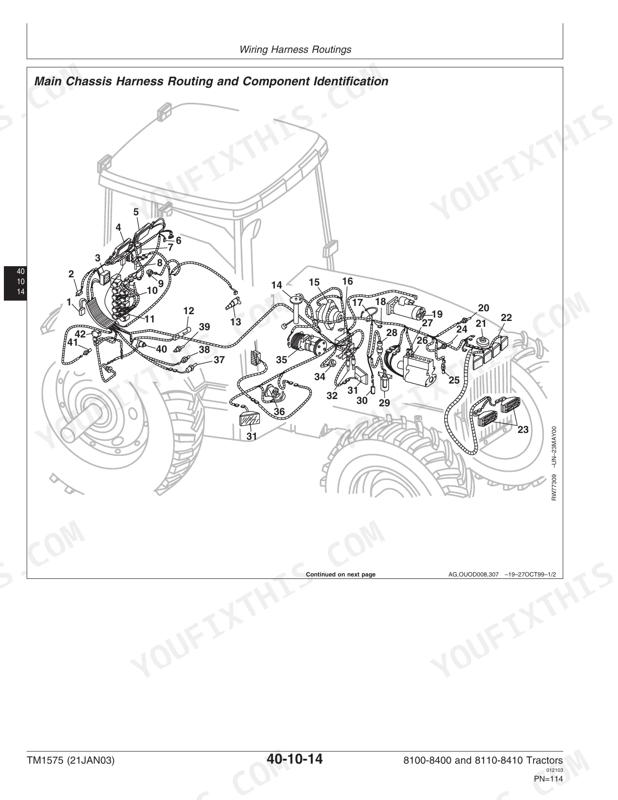
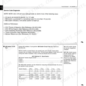
| Electrical | Connectors, Wiring Harness Routings, Charging Circuit, Starting Circuit, Solenoids and Switches, Monitoring Systems and Sensors, Armrest Control, Implement and Accessory Connectors, Convenience and Accessory Components | |
| Power Shift Transmission | Component Removal and Installation, 8100/8200/8300/8400 Transmission Repair, 8110/8210/8310/8410 Transmission Repair | |
| Drive Systems | Rear Differential and Input Quill, Final Drives, Rear PTO, Hydraulic Pump Drive, MFWD Clutch, MFWD Axle Version a, MFWD Axle Version B, Drivelines | |
| Steering and Brakes | Steering Column, Steering Control Assembly, Steering Cylinders, Brake Valve, Brake Components, Trailer Brakes | |
| Hydraulics | Component Removal and Installation, Hydraulic System Repair and Cleanup, Tandem Hydraulic Pump (Steering/Brakes/Charge), Secondary Hydraulic Pump (Hitch/SCV), Filter Bypass, Hitch Valve, Selective Control Valves and Couplers, Hitch, Row Guidance | |
| Miscellaneous | Component Removal and Installation, Front Axle (2-Wheel Drive), Wagon and Pick-Up Hitch | |
| Operator Station | Component Removal and Installation, Heating Ventilating and Air Conditioning, Air Conditioning System, Air Suspension Seat (8000 Series), Air Suspension Seat (8000 Ten Series), Armrest, Cab Door and Windshield | |
| Dealer Fabricated Tools | Fabricated Tools |
Quick Reference Specifications
| Specification | Value | Page |
|---|---|---|
| 8100, 8200, 8300 with 7.6L diesel | ||
| Engine Coolant Capacity (7.6L Engine) | 27.2 L (7.2 gal) | |
| 8400, 8110, 8210, 8310, 8410 with 8.1L diesel | ||
| Engine Coolant Capacity (8.1L Engine, SN 010000-) | 34.0 L (9 gal) | |
| Early 8400 with 8.1L diesel | ||
| Engine Coolant Capacity (8.1L Engine, SN -009999) | 28.4 L (7.5 gal) | |
| All models | ||
| Radiator Pressure Test | 80 kPa (0.8 bar) (12 psi) | |
| Radiator Cap Pressure Test | 60-80 kPa (0.6-0.8 bar) (9-12 psi) | |
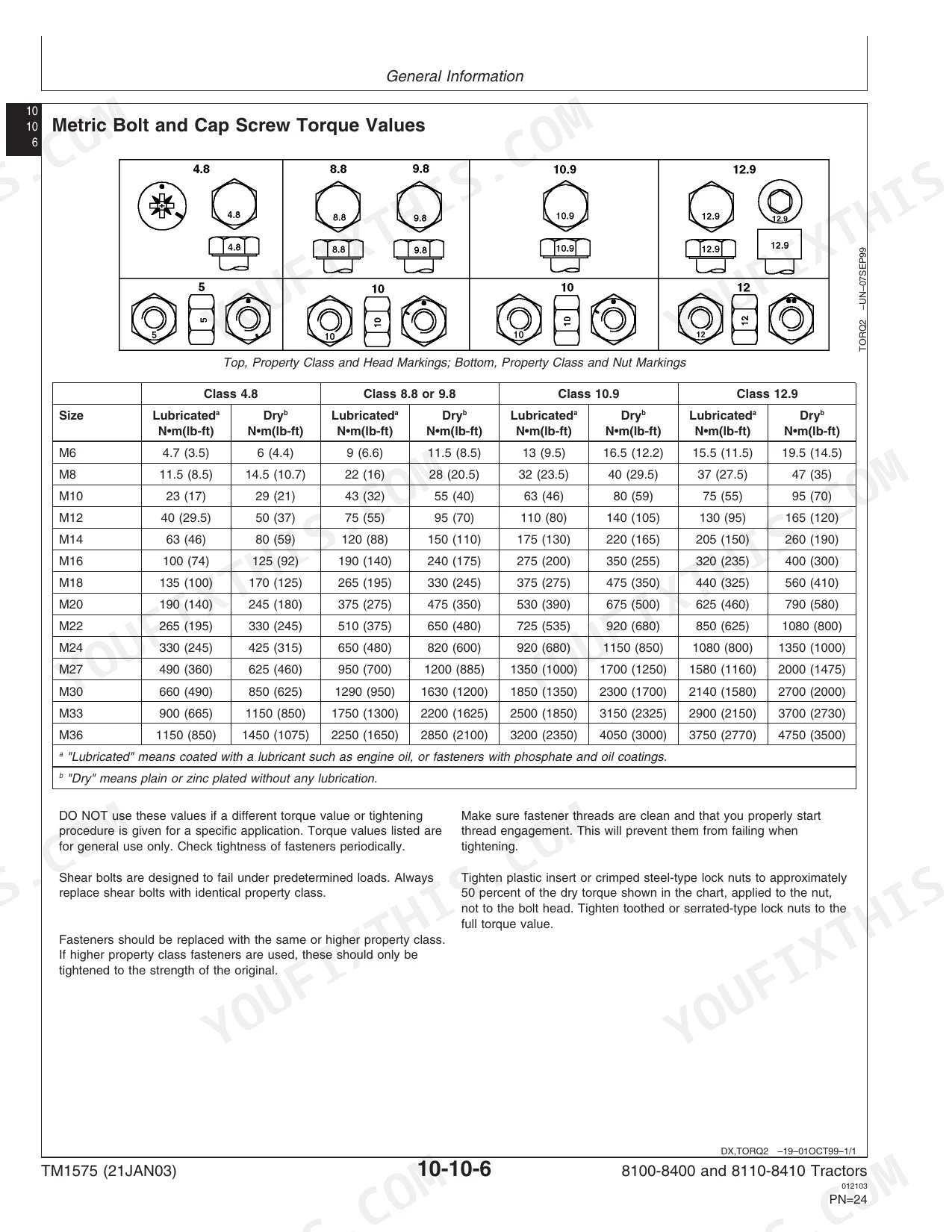
| Fan Drive Support-to-Engine Block Cap Screws Torque | 150 N.m (110 lb-ft) | |
| Gear-Driven Fan Drive Assembly | ||
| Fan Drive Input Shaft Nut Torque | 270 N.m (200 lb-ft) | |
| Gear-Driven and Belt-Driven Fan Drive Assembly | ||
| Fan Drive Output Shaft Nut Torque | 125 N.m (92 lb-ft) | |
| SN -009999 models | ||
| Fan Drive Capacity | 500 mL (0.5 qt) | |
John Deere 8100, 8200, 8300, 8400, 8110, 8210, 8310, 8410 Common Problems This Manual Covers
Engine shuts down mid-field with a CCU 20/21 low oil pressure alarm
Check the crankcase level and oil viscosity first - incorrect oil type is the leading cause on these engines. If the level is correct, replace the oil filter and retest. If the alarm returns with good oil level and fresh filter, use the Electrical section to test the engine oil pressure sensor (CCU 5 out-of-range low is often logged alongside) before suspecting internal pressure loss. The General Information section lists the correct oil spec and change intervals to prevent repeat faults.
Manual Section: EngineHydraulic oil temperature high warning (CCU 15) during normal field work
Low hydraulic oil level and a restricted or overdue filter are the most common causes. Verify the transmission-hydraulic oil level and replace the filter on its service interval as specified in the General Information section. If temperature stays high with clean fluid, the Hydraulics section covers removing and inspecting the tandem hydraulic pump and checking for restricted return flow that drives oil temperature up under load.
Manual Section: HydraulicsClutch slipping under heavy load (PCU 14) with no obvious mechanical cause
PCU 14 is triggered when the clutch pack slips for longer than the allowed time under load. Start by checking whether the operator is riding the clutch pedal - the fault can be caused by a partially closed clutch engagement switch. The Power Shift Transmission section covers testing the clutch valve solenoid circuit (PCU 30) and the engagement switch, and if those test good, the transmission clutch pack inspection and adjustment procedure is in the Component Removal and Installation group for the relevant model generation.
Manual Section: Power Shift TransmissionIntermittent instrument panel faults and sensor errors across multiple CCU codes
Multiple scattered CCU codes on these tractors often trace back to a corroded ground connection or a damaged wiring harness rather than multiple failed sensors. The Electrical section covers the full harness routing for the 8000 and 8000 TEN Series, harness repair procedures and connector pin-out checks. Inspect the main cab ground and the engine harness connectors above the valve cover first - those locations are known entry points for moisture that causes high-resistance grounds and floating sensor signals.
Manual Section: ElectricalFrequently Asked Questions
What engines are covered in the John Deere 8100-8400 and 8110-8410 repair manual?
The 8100, 8200 and 8300 use the 7.6L diesel with 27.2 L (7.2 gal) coolant capacity. The 8400 and the full 8000 TEN Series (8110-8410) run the 8.1L diesel - early builds hold 28.4 L (7.5 gal) and later serial number 010000-up hold 34.0 L (9 gal). The manual lists removal, installation and repair procedures for both engine sizes.
What does CCU 7 error code mean on a John Deere 8300 or 8310?
CCU 7 means the ECU does not match the tractor model - the controller unit is mismatched or has been swapped from a different machine. The Electrical section covers the monitoring system and sensor circuits so you can verify connector wiring, check for controller swaps and confirm the correct ECU is fitted before going further with diagnosis.
What causes the engine oil pressure low (CCU 20/21) STOP ENGINE alarm?
On these tractors CCU 20 and CCU 21 flag a confirmed low oil pressure event that commands an engine shutdown. Common causes are incorrect oil viscosity, a low crankcase level, a clogged oil filter or a failing pressure sensor. The Engine and General Information sections give the oil specification and filter service interval. If the sensor tests in-range and pressure is still low, the Engine Repair section covers checking the oil pump.
How do I fix a PCU 8 transmission not calibrated code on a John Deere 8110 or 8210?
PCU 8 means the Power Shift Transmission has lost its calibration, which can happen after a battery disconnect, an ECU swap or a clutch valve replacement. The Power Shift Transmission section has separate repair and calibration procedures for the 8100-8400 and the 8110-8410 transmissions - you run the calibration sequence from the armrest control as described in the manual to restore proper clutch pack engagement.
Does this manual cover the hydraulic selective control valves and hitch valve?
Yes. The Hydraulics section covers the tandem hydraulic pump (steering, brakes and charge circuit), the secondary hydraulic pump for the hitch and SCVs, filter bypass, the hitch valve, all selective control valves and couplers, the three-point hitch, and row guidance. Test pressures and flow specs are included so you can pinpoint whether a slow or non-responsive SCV is a pump, valve or hitch issue.
How will I receive this John Deere 8100, 8200, 8300, 8400, 8110, 8210, 8310?
You get a 1124-page searchable PDF (27 MB) that downloads instantly after checkout. Open it on your laptop, tablet, or phone, and bring it right to the shop floor.
Am I able to print pages from this John Deere 8100, 8200, 8300, 8400, 8110?
Absolutely. No DRM or copy protection. Print the whole manual or just the pages you need. Any home or office printer works.