


Part of the John Deere Repair Manuals.
All 742 pages of the John Deere PowerTech™ 8.1L Level 9 Technical Manual PDF (OEM #CTM255) zero in on one machine: the PowerTech™ 8.1 L diesel engine and its electronically controlled High Pressure Common Rail fuel system. Inside, you get factory wiring diagrams, a full troubleshooting section covering observable faults and trouble-code diagnostics from cranks-won't-start to irregular misfires, and step-by-step procedures for removing electronic injectors and the high-pressure fuel pump. Specs cover complete torque tables for inch and metric fasteners, your engine sensor values, and full diagnostic specifications. Torque the HPCR injection line fittings to 53 N·m (39 lb-ft); the fuel pump drive gear cap screws go to 61 N·m (45 lb-ft) on a 15.7:1 compression ratio engine holding 345 kPa oil pressure at rated rpm. HPCR fault codes don't guess. Search by keyword, jump to any section via bookmarks, and get this engine running. Note: CTM255 covers only the Level 9 (Tier II) electronic fuel system with the Denso high-pressure common rail — base-engine repair for the same PowerTech 8.1 L lives in a separate manual, CTM86.
What's Inside This John Deere PowerTech™ 8.1L (6081HF070) Manual
| System | Pages | Key Topics |
|---|---|---|
| General | 7-24 | Safety, Engine Identification, Fuels, Lubricants, And Coolant |
| Repair and Adjustments | 25-80 | Electronic Fuel System Repair and Adjustments, Electronic Engine Control Repair and Adjustment, Remove and Install High Pressure Fuel Pump, Remove Electronic Injectors |
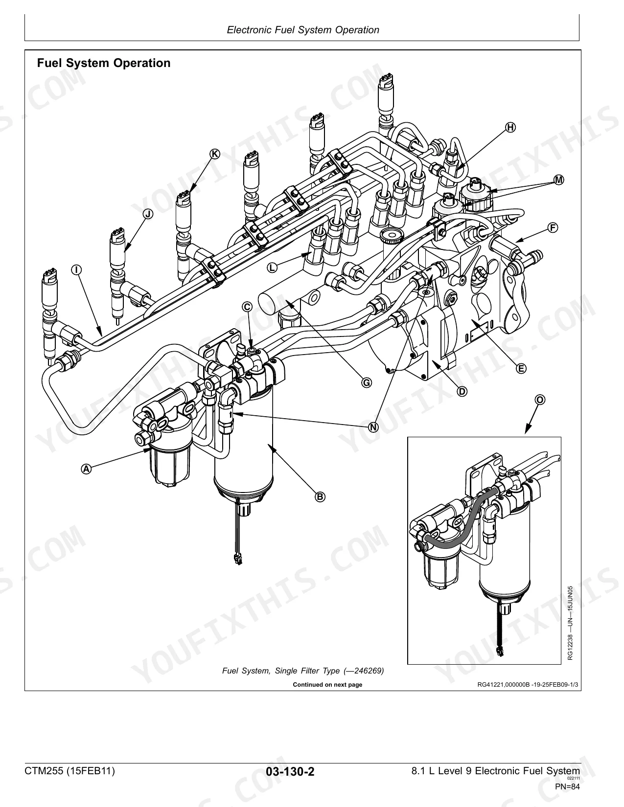
| Theory of Operation | 81-128 | Fuel System Operation, High Pressure Fuel Pump Operation, High Pressure Common Rail (Hpcr) Operation, Electronic Injector (Ei) Operation, Electronic Control System Terminology |
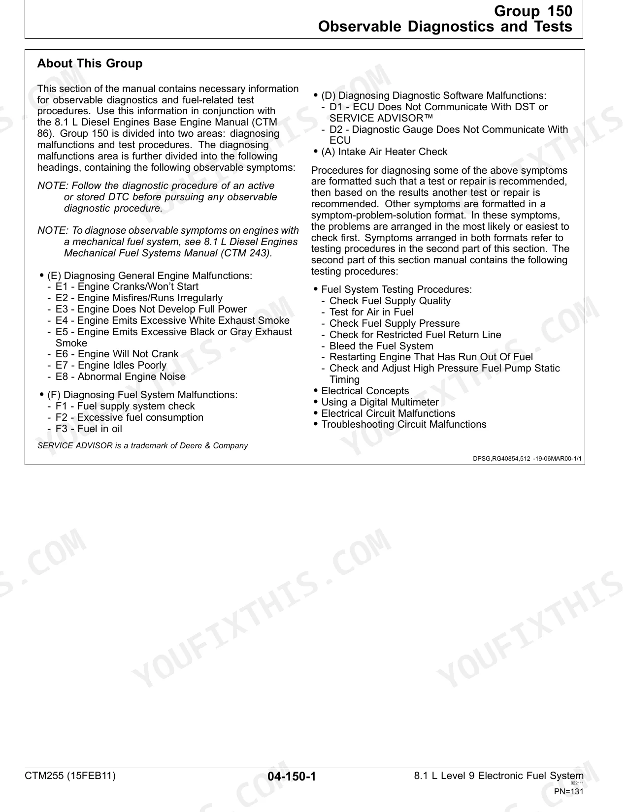
| Diagnostics | 129-658 | Observable Diagnostics and Tests, Trouble Code Diagnostics and Tests, Engine Cranks/Won’t Start Diagnostic Procedure, Fuel Supply System Check Diagnostic Procedure |
| Tools | 659 | Electronic Fuel/Control System Repair Tools, Diagnostic Service Tools, Fuel Inlet Connector Installer, Weather Pack™ Crimping Tool, Digital Multimeter, Connector Adapter Test Kit |
| Specifications | 675-742 | Unified Inch Bolt and Screw Torque Values, Metric Bolt and Screw Torque Values, Fuel System Component Torque Specifications, Engine Sensor Torque Specifications |
Quick Reference Specifications
| Specification | Value | Page |
|---|---|---|
| Fuel Pump Drive Gear-to-Pump Hub Cap Screws—Torque | 61 N∙m (45 lb-ft) | p. 207 |
| Fitting — High Pressure Injection Line to HPCR Fuel Inlets—Torque | 53 N∙m (39 lb-ft) | p. 44 |
| Engine Displacement | 8.1 L | p. 679 |
| Compression Ratio | 15.7:1 | p. 679 |
| Oil Pressure at Rated rpm | 345 kPa | p. 679 |
| Recommended Pressure Cap | 69 kPa | p. 679 |
| Valve Clearance (Cold) Intake | 0.36 mm | p. 679 |
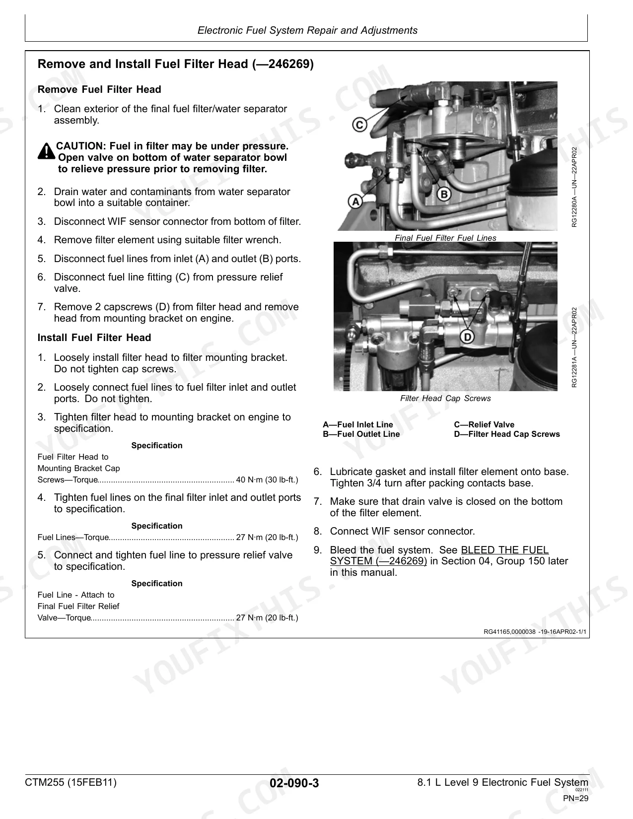
| Fuel Filter Head to Mounting Bracket Cap Screws Torque | 40 N·m | p. 680 |
| Hand Primer Torque | 49 N·m | p. 680 |
| Fuel Transfer Pump Pressure at low idle | 200-240 kPa | p. 683 |
| High Pressure Common Rail Pressure at low idle | 40 MPa | p. 683 |
John Deere PowerTech™ 8.1L (6081HF070) Common Problems This Manual Covers
John Deere PowerTech 8.1L high hour injection pump loose hardware, rough idle and poor engine performance
Inspect the injection pump pointer hardware and timing gears. Torque the fuel pump drive gear-to-pump hub cap screws to 61 N∙m (45 lb-ft) as detailed on page 207. Clear any sheared metal from the timing case and replace the damaged camshaft key.
Manual Section: Engine Misfires/Runs Irregularly Diagnostic Procedure p. 207Excessive blow-by and crankcase pressure, heavy smoke and oil leaking from anywhere on the engine
Test cylinder compression to isolate degraded internal seals. Verify the engine oil pressure at rated rpm reads 345 kPa as specified on page 679. Tear down the block to install a complete overhaul kit, paying close attention to the piston rings and cylinder sleeves.
Manual Section: Diagnostics p. 679Air entering the fuel supply system, engine misfires and prolonged cranking or very hard to start
Bleed air from injector lines 6, 5, and 1. Torque the high pressure injection line to HPCR fuel inlet fittings to 53 N∙m (39 lb-ft) as indicated on page 44. Measure fuel transfer pump pressure at low idle to ensure it reaches 200-240 kPa.
Manual Section: Fuel Supply System Check Diagnostic Procedure p. 44Frequently Asked Questions
How to reset error codes on John Deere PowerTech 8.1L?
Stored Diagnostic Trouble Codes (DTCs) on the diagnostic gauge (Earlier Model) can be cleared by simultaneously pressing and holding the right and left switch for at least 8 seconds. After the display reads "*Send* **DM3 *", the codes are cleared. p. 223
Torque specs for John Deere PowerTech 8.1L cylinder head bolts?
The torque specification for the Carrier-to-Cylinder Head Cap Screws on the John Deere PowerTech 8.1L engine is 61 Nm (45 lb-ft). This specification is found in the Repair Specifications section of the manual. p. 681
What are the common error codes for PowerTech 8.1L engine?
The manual provides a comprehensive list of Diagnostic Trouble Codes (DTCs) for the PowerTech 8.1L engine, including SPN/FMI codes and their descriptions, starting on page 240. Examples include 000028.03 (Throttle Voltage High), 000029.03 (Throttle Voltage High), and 000084.09 (Vehicle Speed Invalid or Missing). p. 240
How to reset engine control module on PowerTech 8.1L
The manual indicates that "Information in RAM is lost when battery voltage to the ECU is removed," which would effectively reset the volatile memory of the Engine Control Unit (ECU). However, it does not provide a specific "reset" procedure for the entire ECU, emphasizing that the ECU is not repairable and should not be opened. p. 117
What do I get after purchasing this John Deere PowerTech™ 8.1L?
This is a 742-page searchable PDF ready for immediate download. Works on any device, so pull it up on your phone while you're under the hood. No shipping, no waiting.
Can I print this John Deere PowerTech™ 8.1L manual?
Absolutely. No DRM or copy protection. Print the whole manual or just the pages you need. Any home or office printer works.
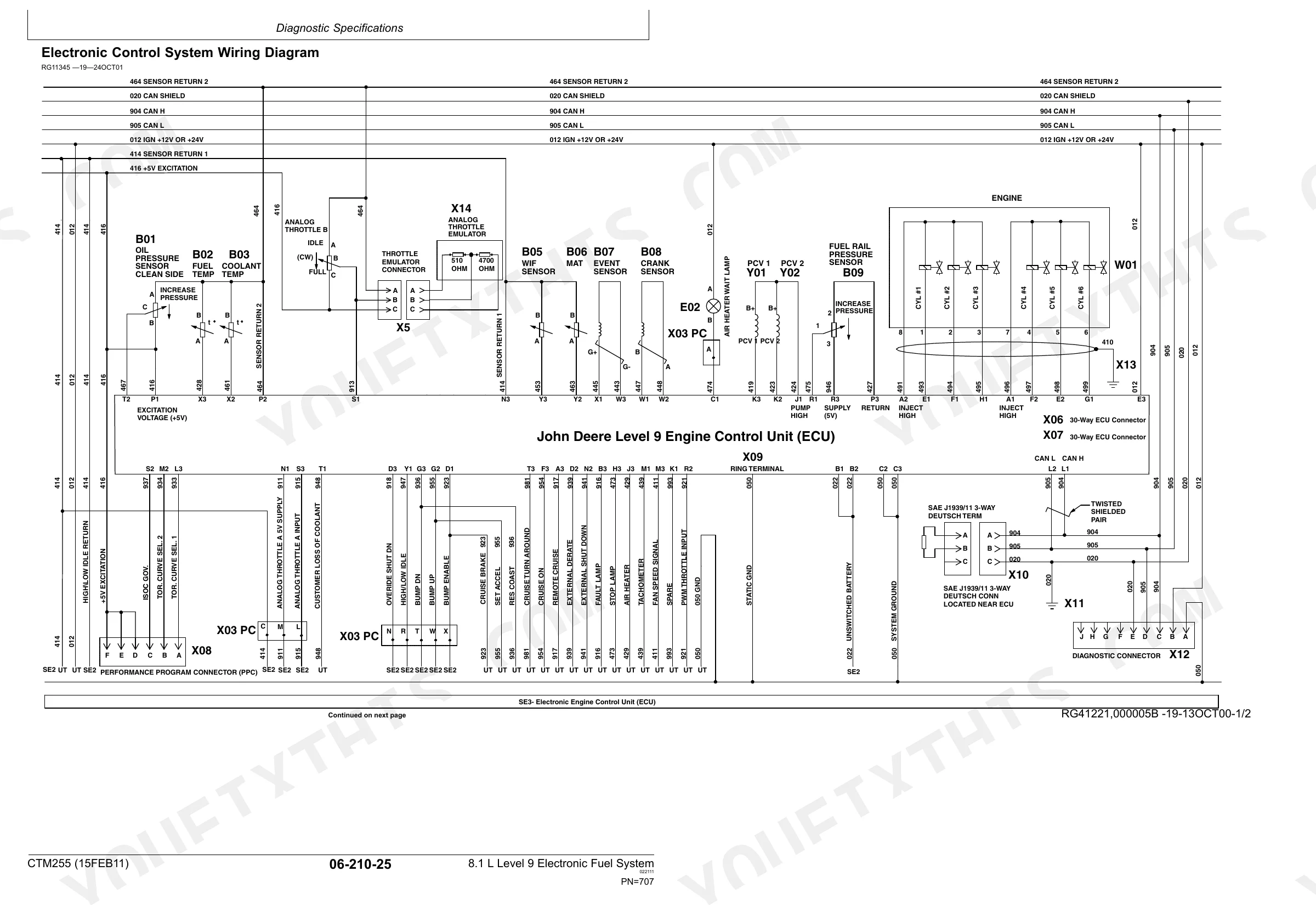
Are there wiring harness diagrams in this John Deere PowerTech™?
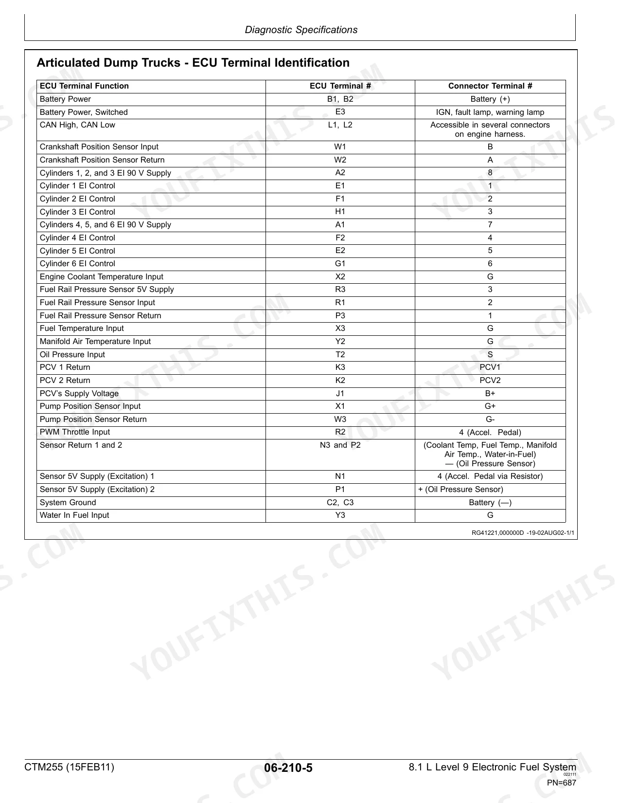
Yes. You'll find an electrical wiring diagram covering the main wiring layout.


