
Part of the John Deere Repair Manuals.
Chasing low oil pressure on a PowerTech? This 450-page John Deere PowerTech 10.5 L and 12.5 L Technical Manual PDF (OEM CTM100) walks you through the 6105HF, 6125HF, 6105HRW, 6125HRW, 6105ADW, and 6125 Tier II diesel engines that power the 9200, 9220, 9300, 9320, and 9400 tractors. Inside: a complete engine rebuild guide covering cylinder head and valves, liners, pistons, rods, and crankshaft, plus break-in and tune-up procedures. You also get a full diagnostics section for excessive oil consumption, high or low oil pressure, and coolant temperature problems, backed by unified inch and metric torque tables. Torque the injector adjusting screw lock nuts to 65 N-m (48 lb-ft) and check intake valve stem-to-bridge clearance at 0.58 mm on a cold engine. Your tractor is down; get factory numbers, not forum guesses. Bookmarked sections and keyword search take you straight to the spec.
What's Inside This John Deere PowerTech 10.5L & 12.5L (6105/6125 Series) Manual
| System | Pages | Key Topics |
|---|---|---|
| General Information | 15-46 | Safety, Engine Identification and Applications, Fuels, Lubricants and Coolant, Engine Serial Number and Option Codes, General Repair Precautions |
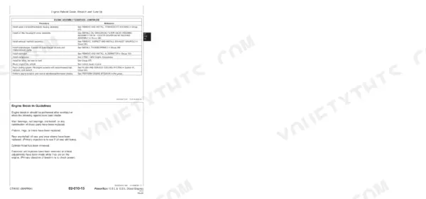
| Repair - Engine Rebuild Guide, Break-In and Tune-Up | 47-74 | Engine Rebuild Guide, Break-In Procedure, Engine Tune-Up, Valve Clearance Check, Compression Test |
| Repair - Cylinder Head and Valves | 75-142 | Cylinder Head Removal and Installation, Valve and Valve Seat Service, Valve Guides and Springs, Rocker Arms and Push Rods, Head Gasket and Torque Sequence |
| Repair - Cylinder Block, Liners, Pistons and Rods | 143-198 | Cylinder Block Inspection, Liner Removal, Installation and Protrusion, Piston and Ring Service, Connecting Rods and Bearings |
| Repair - Crankshaft, Main Bearings and Flywheel | 199-242 | Crankshaft Inspection and Measurement, Main Bearings and Thrust Washers, Front and Rear Crankshaft Seals, Vibration Damper, Flywheel and Ring Gear |
| Repair - Camshaft and Timing Gear Train | 243-270 | Camshaft Removal, Inspection and Installation, Timing Gear Train and Backlash, Camshaft Followers and Bushings, Gear Timing Marks |
| Repair - Lubrication System | 271-286 | Oil Pump, Oil Cooler and Filter, Pressure Regulating Valve, Oil Pan and Pickup, Oil Pressure Specifications |
| Repair - Cooling System | 287-302 | Water Pump, Thermostats, Radiator and Coolant Passages, Fan Drive, Coolant Recovery |
| Repair - Air Intake and Exhaust System | 303-328 | Turbocharger Removal, Inspection and Installation, Aftercooler, Air Intake Manifold, Exhaust Manifold, Air Cleaner |
| Repair - Fuel System | 329-330 | Fuel Injection Pump and Nozzles, Fuel Filters, Fuel Transfer Pump, Bleeding the Fuel System |
| Repair - Starting and Charging Systems | 331-332 | Starter Motor, Alternator, Battery Connections, Charging Circuit Checks |
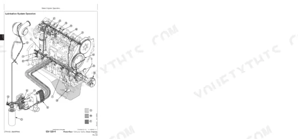
| Theory of Operation | 333-348 | General Engine Operation, Lubrication System Operation, Cooling System Operation, Air Intake and Exhaust Operation, Fuel System Operation |
| Diagnostics | 349-374 | Excessive Oil Consumption, High and Low Engine Oil Pressure, Engine Overheating, Hard Starting, Low Power, Excessive Smoke, Coolant in Oil |
| Tools and Other Materials | 375-410 | Repair Tools and Materials, Diagnostic Service Tools, Dealer-Fabricated Tools, Sealants and Adhesives |
| Specifications | 411-450 | General OEM Engine Specifications, Repair and Wear Limit Specifications, Diagnostic Specifications, Unified Inch and Metric Torque Values |
Quick Reference Specifications
| Specification | Value | Page |
|---|---|---|
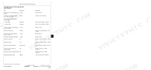
| Electronic Unit Injector—Preload | 0.00 mm (in.) clearance plus 1/2 turn in (180°) | p. 417 |
| Electronic Unit Injector Adjusting Screw Lock Nuts—Torque | 65 N•m (48 lb-ft) | p. 417 |
| Thermostat Test—Rating | 82°C (180°F) | p. 434 |
| Thermostat Test—Initial Opening (Range) Temperature | 80—84°C (175—182°F) | p. 434 |
| Valve Stem-to-Bridge Clearance (Engine Cold)—Intake Valve—Clearance | 0.58 ± 0.05 mm (0.023 ± 0.002 in.) | p. 417 |
| Valve Stem-to-Bridge Clearance (Engine Cold)—Exhaust Valve—Clearance | 1.08 ± 0.05 mm (0.043 ± 0.002 in.) | p. 417 |
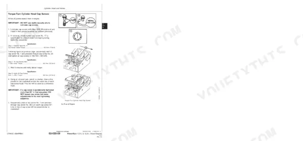
| Cylinder Head Cap Screw Torque—Step 1 (No. 17 Cap Screw Initial Torque) | 100 N•m (74 lb-ft) | p. 134 |
| Cylinder Head Cap Screw Torque—Step 2 (All Cap Screws Initial Torque) | 163 N•m (120 lb-ft) | p. 134 |
| Garrett Turbocharger Shaft—Radial Bearing Clearance (Allowable Movement) | 0.076—0.165 mm (0.003—0.0065 in.) (measured on center of shaft) | p. 435 |
| Borg Warner Turbocharger Shaft—Radial Bearing Clearance (Allowable Movement) | 0.56—0.81 mm (0.022—0.032 in.) (measured on end of shaft) | p. 435 |
| Rear Oil Seal Housing Cap Screws—Torque | 25 N•m (18 lb-ft) | p. 427 |
| Rear Oil Seal-to-Housing Cap Screws—Torque | 15 N•m (11 lb-ft) | p. 427 |
John Deere PowerTech 10.5L & 12.5L (6105/6125 Series) Common Problems This Manual Covers
John Deere PowerTech 10.5L diesel making milky gray oil on dipstick, coolant level dropping
Check the dipstick for milky, gray oil and pressure test the cooling system using the troubleshooting procedures on page 355. Remove the coolant pump and inspect the seal and weep hole for leakage. Replace the seal or pump assembly, drain contaminated oil, install a new filter, and recheck the dipstick after 10 hours of runtime.
Manual Section: Observable Diagnostics and Tests p. 355Coolant disappearing with no external leak on high-hour engine, oil smells like antifreeze
Drain the coolant and pull the oil pan to check for coolant intrusion. Remove pistons and liners, then inspect liner outer walls for cavitation pitting. Measure liner standout with a 0.001 in. dial indicator before final assembly, and maintain supplemental coolant additive at the test intervals listed on page 37 to stop future erosion.
Manual Section: Cylinder Block, Liners, Pistons, and Rods Repair and AdjustmentsEngine knocking under load at operating temperature, oil pressure gauge reading low
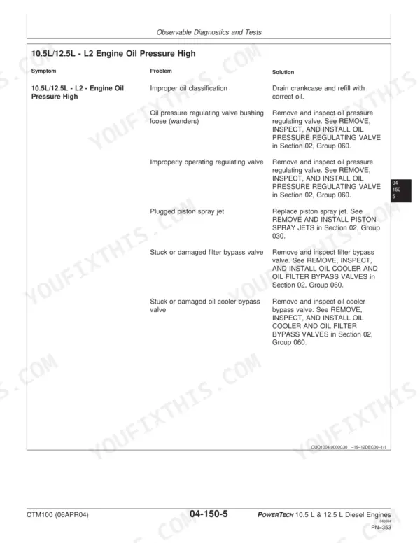
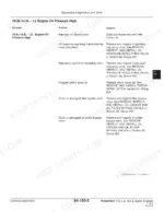
Verify oil level on the dipstick and replace the filter before condemning anything. Warm the oil to operating temperature, roughly 100°C (212°F), then check pressure with a master gauge using the diagnostic procedures on page 355. If pressure stays low, inspect the oil pressure regulating valve and check camshaft lobes for wear.
Manual Section: Observable Diagnostics and Tests p. 355Engine cranks slowly or fails to start in cold weather, white smoke while cranking
Load test the batteries first; a healthy battery holds above 9.6 volts under load at 21°C (70°F). Clean and tighten cable connections, then check starter and alternator condition. Replace a plugged fuel filter and drain stale fuel. Test the coolant heater for continuity and use it below freezing to ease cranking.
Manual Section: Starting and Charging Systems Repair and AdjustmentsCoolant temperature climbs above normal under heavy load, overflow tank pushing coolant out
Check coolant level and inspect the belt tensioner spring tension before deeper teardown. Pressure test the cooling system and radiator cap following the troubleshooting procedures on page 355. Remove the thermostats and suspend them in water heated to 100°C (212°F); replace any thermostat that fails to open fully, and clean radiator fins.
Manual Section: Cooling System Repair and AdjustmentsFrequently Asked Questions
What are the torque specifications for John Deere 12.5L turbocharger bolts?
The torque specifications for the turbocharger bolts on a John Deere 12.5L engine are 50 N•m (37 lb-ft) for the turbocharger-to-exhaust manifold, oil inlet fitting, and oil return pipe-to-turbocharger cap screws. These values are critical for proper installation and preventing leaks. p. 318
What are the replacement specifications for Fuel filter element?
This manual (CTM100) refers to companion manuals CTM115 and CTM188 for the replacement procedures and specifications of fuel filter elements, as these procedures are related to the electronic fuel systems. For complete details, consult the specified CTMs. p. 58
What are the replacement specifications for Injectors / injection nozzles?
This manual (CTM100) refers to companion manuals CTM115 and CTM188 for the replacement procedures and specifications of electronic unit injectors, as these procedures are related to the electronic fuel systems. For detailed instructions, refer to the appropriate fuel system repair manual. p. 59
What type of engine oil should be used for break-in on a new or rebuilt John Deere 10.5L or 12.5L diesel engine?
For break-in on a new or rebuilt John Deere 10.5L or 12.5L diesel engine, John Deere ENGINE BREAK-IN OIL should be used. If unavailable, a diesel engine oil meeting API Service Category CE, CD, CC, or ACEA Oil Sequence E1 or E2 can be used for the first 100 hours of operation. p. 34
What are the valve stem-to-bridge clearance specifications for the John Deere 10.5L and 12.5L diesel engines (engine cold)?
For a cold engine, the intake valve stem-to-bridge clearance should be 0.58 ± 0.05 mm (0.023 ± 0.002 in.), and the exhaust valve stem-to-bridge clearance should be 1.08 ± 0.05 mm (0.043 ± 0.002 in.). These clearances are adjusted using a JDG1333 Feeler Gauge Set. p. 80
What format is this John Deere Powertech 10.5 L & variants manual in?
You get a 450-page searchable PDF that downloads instantly after checkout. Open it on your laptop, tablet, or phone, and bring it right to the shop floor.
Is this John Deere Powertech 10.5 L & variants Technical Manual printable?
Yes. Print the sections you need to take out to the shop for your own use. Standard letter or A4 paper works.








Reviews
There are no reviews yet.