
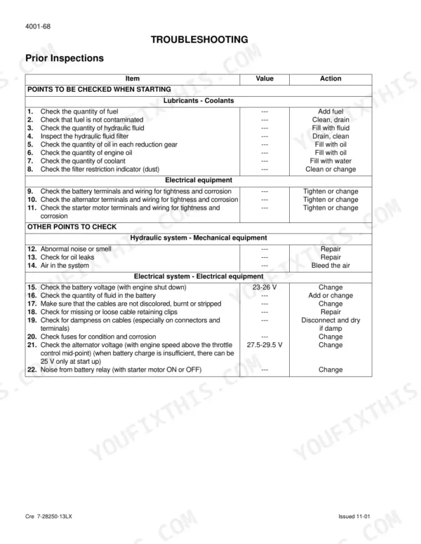
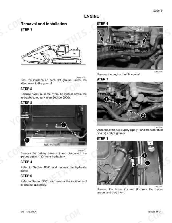


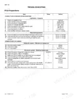
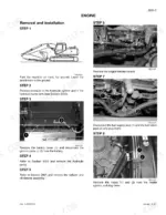
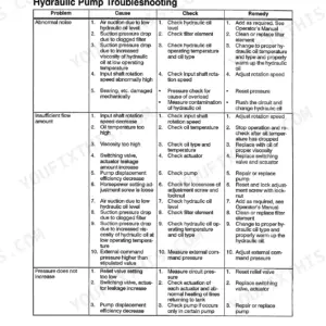
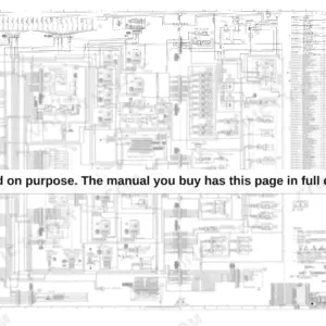
Engine removal, undercarriage rebuilds, drive train teardown, and the complete hydraulic circuit: the Link-Belt 130LX service manual PDF walks each system end to end, 594 pages issued under factory book number Cre 7-28141-13LX for the 130LX crawler excavator. Wiring diagrams and large format hydraulic schematics anchor an electrical section that claims a hefty share of the book, from component locations through the main and engine electronic control boxes. Track sets, rollers, sprockets, and the idler with its tension shock absorber each get their own removal and installation procedures; the swing motor and main control valve come apart in full disassembly sequences. Measure track chain wear against the 1.1 in standard and replace at the 0.71 in limit; torque M12 cap screws to 43.4 lb-ft (58.8 Nm). Diagnosing travel drift without factory pressure settings is a lost afternoon. Bookmarked, with a real text layer you can search, this PDF is bought once and yours for the life of your machine.
What's Inside This Link-Belt 130LX Manual
| System | Pages | Key Topics |
|---|---|---|
| General Information | 5-36 | Safety, Standard Torque Data |
| Engine | 37-48 | Removal and Installation of the Engine, Radiator and Oil-Cooler |
| Fuel System | 49-54 | Removal and Installation |
| Electrical System | 55-158 | Location of Components, Basic Operating Principles, Troubleshooting |
| Undercarriage | 159-218 | Removal and Installation of the Tracks Set, Removal and Installation of a Set of Rubber Tracks, Upper and Lower Rollers, Sprocket, Idler Wheel and Tension Shock Absorber |
| Drive Train | 219-278 | Drive Motor and Final Drive Transmission Removal and Installation, Drive Motor and Final Drive Transmission Disassembly and Assembly, Swing Reduction Gear, Removal and Installation |
| Undercarriage Hydraulics | 279-288 | Bleeding Air, Vacuum Pump, Cleaning Hydraulic System |
| Specifications, Troubleshooting, and Checks | 289-316 | Hydraulic Pressure Settings, Pilot System Relief Valve, Travel Drift, Swing Motor Leaks, Travel Motor Leaks |
| Hydraulic Sump Tank and Main Hydraulic Pump | 317-332 | Hydraulic Sump Tank Removal, Main Hydraulic Pump Removal, Pilot Pump Removal, Hydraulic Pump Coupling |
| Main Hydraulic Control Valve | 333-387 | Main Control Valve Removal, Arm Load Holding Block, Boom Load Holding Block, Swing Priority Block, Semi-Parallel Valve Block |
| Attachment Cylinders and Valves | 388-426 | Non-Return Check Valves, Boom Relief Valve, Arm Relief Valve, Boom Cylinder Disassembly, Arm Cylinder Disassembly, Bucket Cylinder Disassembly |
| Joystick and Pedal Controls | 427-444 | Hand Joystick Control Disassembly, Travel Pedal Control Disassembly, Inspection of Joystick Components |
| Solenoid Valves and Cushion Control | 445-458 | Six Stack Solenoid Valve, Cushion Control Disassembly, Solenoid Valve Inspection |
| Hose Burst Check Valve and Rotating Joint | 459-478 | Hose Burst Check Valve, Rotating Joint Disassembly, Rotating Joint Assembly |
| Swing Motor and Hydraulic Functions | 479-536 | Hydraulic Swing Motor Disassembly, Relief Valve, Hydraulic Functions, Travel Circuits, Swing Circuits, Boom Raising Circuit |
| Upperstructure | 537-594 | Turntable and Counterweight, Boom, Arm and Bucket, Seat and Safety Belt, Cab and Cab Equipment, Air Conditioning Troubleshooting, Air Conditioning Unit Disassembly and Assembly |
Quick Reference Specifications
| Specification | Value | Page |
|---|---|---|
| Cap Screw M6 Tightening torque | 5.1 lb-ft / 6.9 Nm | p. 11 |
| Cap Screw M8 Tightening torque | 14.5 lb-ft / 19.6 Nm | p. 11 |
| Track chain dimension a (Standard) | 1.1 in | p. 27 |
| Track chain dimension a (Limit) | 0.71 in | p. 27 |
| Ground pressure with 19.68 in track pads | 5.66 psi | p. 21 |
| Ground pressure with 23.6 in track pads | 4.79 psi | p. 21 |
| Idler wheel dimension Ø a (Standard) | 20.08 in | p. 24 |
| Idler wheel dimension Ø a (Limit) | 19.92 in | p. 24 |
| Upper roller dimension Ø a (Standard) | 4.72 in | p. 25 |
| Upper roller dimension Ø a (Limit) | 4.41 in | p. 25 |
| Toothed wheel dimension a (Standard) | 2.32 in | p. 23 |
| Toothed wheel dimension a (Limit) | 2.09 in | p. 23 |
Link-Belt 130LX Common Problems This Manual Covers
Link-Belt 130LX final drive leaking gear oil, growling noise from travel motor while tracking
Drain the final drive and check the oil for metal flake. Inspect the floating seals for weeping around the sprocket hub. Torque the level, fill, and drain plugs to 3.6 to 8 lb-ft per page 220. If you pull the drive motor, torque its cap screws to the final drive at 102 to 138 lb-ft, listed on page 225.
Manual Section: Drive Train p. 219Track keeps going loose, chain jumping sprocket teeth, rollers and idler wheel wearing fast
Measure track sag first: correct tension is 9.45 to 10.24 inches, spec on page 21. Check chain link height against the 0.71 inch wear limit on page 27; past that, adjustment won't save the chain. Inspect sprocket teeth for hooking, then torque track pad bolts to 289 to 317 lb-ft from the chart on page 33.
Manual Section: Undercarriage p. 159Rattling noise from pump compartment behind engine, all hydraulic functions weak or dead
Check the pump coupling before condemning the pump; a chewed-up coupling insert makes this exact rattle. Remove the pump, inspect the splines, and torque the main pump to coupling flange screws to 70 to 89 lb-ft per page 325. Then verify main relief pressure at 4970 plus or minus 45 psi, spec on page 20.
Manual Section: Hydraulic Sump Tank and Main Hydraulic Pump p. 317Machine pulls to one side while traveling, one track noticeably slower than the other
Test P1 and P2 pump pressures against each other with the machine tracking; a weak side points at pump or travel motor leakage. Verify main relief holds 4970 plus or minus 45 psi from page 20, then run the travel mistracking and travel motor leak checks in the section starting on page 289.
Manual Section: Specifications, Troubleshooting, and Checks p. 289Hydraulic oil running hot after a few hours, radiator and oil cooler packed with debris
Blow out the radiator and oil cooler cores from the fan side with compressed air, then check fin condition for crushed passages. Verify hydraulic oil level against the 32.5 gallon system capacity on page 19. If the radiator comes out for cleaning, torque its M12 mounting bolts to 47 to 53 lb-ft per page 33.
Manual Section: Engine p. 37Frequently Asked Questions
How do I access the diagnostic mode on a Link-Belt 130LX?
To access the diagnostic mode, press the travel mode and work mode switches simultaneously for a minimum of 3 seconds. Then, press the automatic mode switch to navigate through the diagnostic screens. p. 104
How do I reset a Link-Belt 130LX fault code?
To erase data or reset the system, press the work mode switch for a minimum of 10 seconds until the audible warning device sounds. Alternatively, in the diagnostic mode, if an error code is changed to zero, the data is also erased. p. 104
What are the torque specifications for Link-Belt 130LX track pad bolts?
The torque specification for the track pad bolts on the Link-Belt 130LX is 289 to 317 lb-ft. p. 33
What is the engine torque specification for a Link-Belt 130LX?
The engine for the 130LX produces a maximum torque of 239 lb-ft at 1600 rpm. p. 19
What is the hydraulic fluid capacity for the Link-Belt 130LX?
The total hydraulic system capacity for the 130LX is 32.5 gallons, with a reservoir capacity of 19 gallons. p. 19
How will I receive this Link-Belt 130LX Service Manual?
Immediate download of the complete 594-page searchable Service Manual. Access it on any device, from a laptop at your desk to a phone in the field.
Can I print this Link-Belt 130LX manual?
Yes. Many mechanics print the section they need for their own shop and bring it to the bench.



Reviews
There are no reviews yet.