
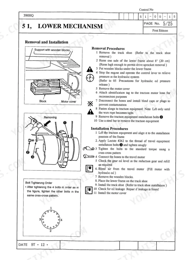

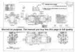
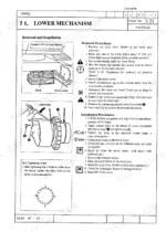
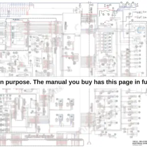
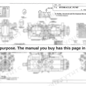
Swing motor wear limits on a Quantum-series machine live in exactly one place, and this Link-Belt 3900Q shop manual PDF is it: 624 pages of factory service data for your 3900Q excavator, from undercarriage rollers to hydraulic cylinders. Hydraulic schematics trace the pilot and main circuits through pump, control valve, and travel motor, while wiring diagrams map the electrical system and maintenance standards tables give you wear limits for rollers, idlers, and reduction gears. Teardown procedures for the travel and swing motor assemblies fill a large share of the book, each closing with reassembly torques and troubleshooting charts. Check brake release signal pressure at 426.5 to 710.9 psi, and inspect hoses and lines every 50 hours. A final drive half apart is no time to hunt a bearing spec. Bookmarked and text-searchable, this PDF also prints clean, so the pages can ride the bench and take the grease.
What's Inside This Link-Belt 3900Q Manual
| System | Pages | Key Topics |
|---|---|---|
| Explanation | 3-14 | Contents, Safety, Introduction, Symbols Used, Precautions, Standard Torque Specifications, Numerical Value Conversion Table |
| General | 15-44 | Safety, Precautions |
| Specifications | 45-70 | Major Equipment Specifications, Filters, Fluids and Lubricants |
| Performance | 71-78 | Main Body Weight, New Machine Performance Check List, Suspension Performance |
| Main Body Disassembly and Servicing Procedures | 79-138 | Lower Mechanism, Upper Mechanism, Attachment, Maintenance Standards |
| Major Components Disassembly and Servicing Procedures | 139-190 | Tightening Torque for Major Parts, Take-Up Roller, Recoil Spring, Upper Roller, Lower Roller, Rotating Joint |
| Hydraulic Pump Instruction and Maintenance | 191-214 | Hydraulic Pump Handling, Regulator Instruction, Pump Disassembly, Pump Reassembly, Maintenance Standards |
| Travel Mechanism Motor Assembly | 215-366 | Motor Assembly, Reduction Gear, Troubleshooting, Maintenance Standards, Special Jigs |
| Swing Mechanism Motor Assembly | 367-478 | Swing Motor Assembly, Reduction Gear, Relief Valve Maintenance, Troubleshooting, Structure Diagrams |
| Control Valve Operations and Maintenance | 479-528 | Control Valve Principles, Disassembly, Reassembly, Relief Valve Maintenance, Troubleshooting |
| Hydraulic Cylinder Specifications and Maintenance | 529-624 | Cylinder Structure, Disassembly Procedures, Reassembly Procedures, Maintenance Standards, Troubleshooting |
Quick Reference Specifications
| Specification | Value | Page |
|---|---|---|
| Oil seal inclination allowance | 0.008 inch per 3.937 inch (0.2 mm at 100 mm) | p. 31 |
| Fuel tank mounting bolts torque | 184.4-213.4 ft lbs (252-289.3 N-m) | p. 53 |
| Fuel tank sensor cover bolts torque | 9.4 ft lbs (12.75 N-m) | p. 54 |
| Maintenance Interval for Hoses and Lines | Every 50 hours | p. 69 |
| Brake release port signal pressure | 426.5 - 710.9 psi (30 - 50 kgf/cm²) | p. 409 |
| Relief valve adjustment shim pressure change | 71.09 psi (5 kgf/cm²) | p. 412 |
| Rated Pressure | 568.7 psi (3.92 MPa) | p. 619 |
| Rated Voltage | DC 24 Volt | p. 589 |
| Travel Motor Suction Capacity | 7.9/5.0 in³/rev | p. 49 |
| Travel Motor Working Pressure | 4975 psi | p. 49 |
| Engine Displacement | 504.7 in³ | p. 53 |
| Engine Rated Horsepower | 138 kW | p. 53 |
Link-Belt 3900Q Common Problems This Manual Covers
Link-Belt 3900Q swing brake will not release, swing motor dead while travel and boom work fine
Test pilot pressure at the brake release port; you need 426.7 psi (2.9 MPa) there per page 426 before the mechanical brake lets go. If pressure is low, check the brake solenoid valve: it runs on DC 24 volts. Measure case drain too; more than 1.32 gpm from the swing motor means internal wear, not a brake problem.
Manual Section: Swing Motor Troubleshooting p. 426Machine loses swing and one travel side after sitting unused for months, controls feel dead
Remove and clean the sticking control valve spools; varnish from oxidized oil glues them down after long storage. Work the spool sticking checks in the Control Valve section starting on page 479. Drain the system, refill the 58 gallon sump tank with fresh oil, and cycle every function slowly until full stroke returns.
Manual Section: Control Valve Operations and Maintenance p. 479Hydraulic oil overheats within an hour when running a hammer or mulcher attachment
Check oil temperature at the sump tank; keep it under the recommended 149°F (65°C) limit on page 201, and never past 176°F or the seals cook. Verify the pump still delivers its rated 56.2 gpm maximum output shown on page 240. An attachment demanding more flow than that parks the circuit on relief and boils the oil.
Manual Section: Hydraulic Pump Instruction and Maintenance p. 201Engine loses power under load and will not pull a full bucket uphill
Check fuel delivery first: remove and clean the primer pump inlet screen and banjo bolt screens, they plug with tank debris and starve the engine. Drain water and sediment from the fuel tank while you are there. If the tank comes off for flushing, torque the mounting bolts to 186-213 ft lbs per the chart on page 143.
Manual Section: Major Components Disassembly and Servicing Procedures p. 143One track drags and machine will not travel straight, worse in high speed range
Check travel reduction gear oil first; each final drive holds 2.2 gallons per page 290. Then test the counterbalance valve and 2-speed circuit following the Travel Mechanism section starting on page 215, since a stuck counterbalance spool on one side pulls the machine off line. Torque travel motor bolts to 664-775 ft lbs on reinstall.
Manual Section: Travel Mechanism Motor Assembly p. 215Frequently Asked Questions
What are the torque specifications for the Link-Belt 3900Q track shoe bolts?
The tightening torque for the track shoe bolts (M20) is 557-687 ft lbs (755-932 N m). p. 143
How do I find the torque specifications for the Link-Belt 3900Q?
Torque specifications for major components are listed in the 'Standard Torque Specifications' section on page 34 and the 'Tightening Torque for Major Parts' section on page 143. p. 34
What is the standard oil capacity for the travel mechanism reduction gear?
The standard oil capacity for the travel mechanism reduction gear is 2.2 gallons (8.5 liters). p. 293
What is the replacement interval for the engine oil filter?
The engine oil filter (full flow) should be replaced every 250 hours. p. 67
How do I release hydraulic pressure from the circuit before maintenance?
To release hydraulic pressure, lower the attachment to the ground, turn the starter switch to OFF, then ON, ensure the lever lock is released, move the operation levers back and forth/left and right about 5 times, and turn the starter switch to OFF. p. 24
How quickly can I access this Link-Belt 3900Q manual after buying?
You get a 624-page searchable PDF that downloads instantly after checkout. Open it on your laptop, tablet, or phone, and bring it right to the shop floor.
Can I print pages of this Link-Belt 3900Q manual for my own shop?
Yes. Many buyers print one chapter at a time for their own shop and keep the rest on a tablet.


Reviews
There are no reviews yet.