
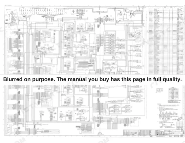


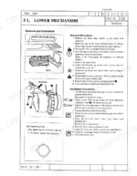

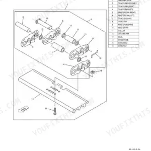
A travel motor rebuild on a 2800 stalls fast without the factory numbers, and this 716-page Link-Belt 2800, 3400 shop manual PDF (OEM ID 817) is where those numbers live for both hydraulic excavators. Hydraulic schematics trace the pump, regulator, and control valve circuits, and the control valve section alone takes up roughly the last third of the book. Disassembly procedures run from the undercarriage rollers and recoil spring up through the swing motor and rotating joint, each closing with maintenance standards you can measure worn parts against. Keep casing inner pressure under 28.4 psi (2.0 kgf/cm²) during travel motor work, and pull the upper roller installation bolts to 384-445 ft lbs (521-608 N·m). One missing spec can park a whole crew for a day. This bookmarked, text-searchable PDF puts that number in front of you and the 2800 or 3400 back on the meter.
What's Inside This Link-Belt 2800, 3400 Manual
| System | Pages | Key Topics |
|---|---|---|
| Shop Manual Explanation | 3-46 | Contents, Safety, Introduction, Symbols Used, Precautions, Standard Torque Specifications, Numerical Value Conversion Table |
| General | 47-84 | Lower Mechanism, Engine, Excavator Attachment |
| Performance | 85-102 | Main Body Weight, New Machine Performance Check List, Suspension Performance |
| Main Body Disassembly and Servicing Procedures | 103-182 | Lower Mechanism, Upper Mechanism, Attachment, Maintenance Standards |
| Major Components Disassembly and Servicing Procedures | 183-234 | Tightening Torque for Major Parts, Take-Up Roller, Upper Roller, Lower Roller, Recoil Spring, Rotating Joint |
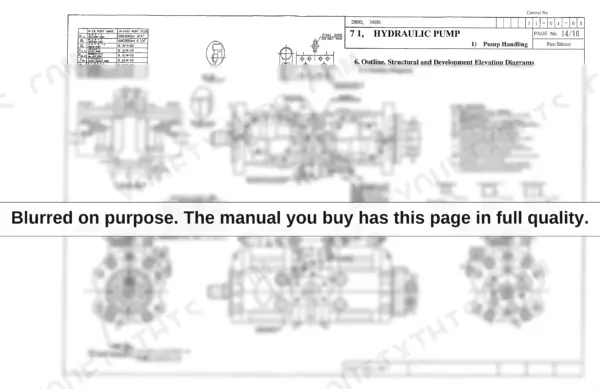
| Hydraulic Pump Handling | 235-258 | Pump Handling, Pump Maintenance, Regulator Handling, Regulator Maintenance |
| Hydraulic Pump Maintenance | 259-280 | Pump Main Body Disassembly, Pump Main Body Maintenance Standards, Structure Diagram, Development Elevation |
| Regulator Handling | 281-306 | Regulator Specifications, Fluid Control, Horsepower Control, Qmax Cut Control, Regulator Adjustment |
| Regulator Maintenance | 307-326 | Regulator Disassembly, Regulator Inspection, Regulator Reassembly, Structure Diagram |
| Travel Mechanism | 327-450 | Travel Motor Assembly, Travel Motor Maintenance, Reduction Gear Disassembly, Reduction Gear Assembly |
| Swing Mechanism | 451-524 | Swing Motor Assembly, Swing Mechanism Maintenance, Relief Valve Disassembly, Swing Brake Function |
| Control Valve | 525-716 | Control Valve Operations, Relief Valve Maintenance, Stack Valve Structure, Solenoid Valve Maintenance |
Quick Reference Specifications
| Specification | Value | Page |
|---|---|---|
| All Models | ||
| Fuel tank mounting bolts torque | 252-289 N·m | p. 63 |
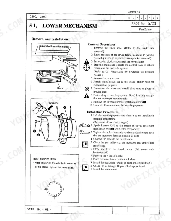
| Travel equipment installation bolts | 197-230 ft lbs (267-312 N·m) | p. 109 |
| Allowable casing inner pressure | 28.4 psi (2.0 kgf/cm²) | p. 244 |
| Operating temperature range | -4°F to 176°F (-20°C to 80°C) | p. 245 |
| Pin (15) protrusion beyond flange (10) | 1.055" - 1.094" (26.8mm - 27.8mm) | p. 433 |
| Hydraulic oil temperature | Below 176°F (80 °C) | p. 609 |
| Buffer ring bending radius | 6 mm | p. 621 |
| Hydraulic oil cooler capacity | 300 cm3 | p. 716 |
| 2800 | ||
| 2800 Lower Total Weight | 17,260 lbs | p. 47 |
| 2800 Engine Rated Horsepower | 128 PS | p. 59 |
| 3400 | ||
| 3400 Lower Total Weight | 20,240 lbs | p. 47 |
| 3400 Engine Rated Horsepower | 153 PS | p. 60 |
Link-Belt 2800, 3400 Common Problems This Manual Covers
Link-Belt 2800 hydraulic pump grinding and whining under load, boom and bucket slow to lift
Check hydraulic tank oil level and inspect the suction line for air leaks; aeration makes a pump growl and kills flow. Bleed the pump housing, then work through the pump handling procedures starting on page 235. If noise continues after any pump work, torque the mounting hardware per the chart on page 187 and retest under load.
Manual Section: Hydraulic Pump Handling p. 235Hydraulic oil overheats after an hour of digging, cylinders drift and lose power
Clean the hydraulic oil cooler fins with compressed air and check for crushed tubes or trash packed in the core. Measure oil temperature during work; it must stay below 176°F (80°C) as noted on page 609. If one cylinder runs hotter than the others, suspect internal leakage past the piston seals and reseal that cylinder.
Manual Section: Cylinder Troubleshooting p. 609Travel motor whines and one track runs slower than the other on straight travel
Check track tension on both sides first, then swap travel lines side to side to isolate the fault. If the problem follows the motor, work through the travel mechanism section starting on page 327 and inspect the counterbalance valve for a sticking spool. After motor removal, torque the travel motor bolts to 266.6-311.6 N·m per page 187.
Manual Section: Travel Mechanism p. 327Track adjuster grease fitting leaks, tracks sag and chain jumps the sprocket
Replace the leaking grease fitting on the track adjuster and pump the tension cylinder back up before condemning anything else. Inspect the take-up roller and recoil spring; removal steps start in the service procedures on page 109. On reassembly, torque the take-up roller installation bolt to 197-230 ft lbs (267-312 N·m) per page 112, then recheck sag.
Manual Section: Main Body Disassembly and Servicing Procedures p. 112Engine loses power intermittently and stalls, runs fine again after sitting a few minutes
Clean the fuel primer pump inlet screen and blow out the pickup line; a plugged screen starves the engine under load and clears itself at rest. Drop and flush the fuel tank if debris keeps coming back. On reinstall, tighten the six tank mounting bolts to 186-213 ft lbs (252-289 N·m) per page 63, then bleed the system.
Manual Section: General p. 63Frequently Asked Questions
What are the torque specifications for the hexagonal head bolts on the Link-Belt 2800 and 3400?
For M16 hexagonal head bolts, the tightening torque is 101.3 ft lbs (137.2 N m). For M20 hexagonal head bolts, the tightening torque is 202.6 ft lbs (274.0 N m). p. 34
What is the replacement interval for hydraulic oil and filters when using a hydraulic hammer?
The replacement interval for hydraulic oil and filters when using a hydraulic hammer depends on the frequency of use. For 100% usage, the interval is every 100 hours. For 40% usage, it is every 300 hours. For 20% usage, it is every 600 hours. For 10% usage, it is every 800 hours. p. 84
What is the standard oil amount for the reduction gear in the travel mechanism?
The standard oil amount for the reduction gear in the travel mechanism is 1.24 gallons (4.7 liters). p. 334
What is the tightening torque for the travel motor installation bolts?
The tightening torque for the travel motor installation bolts is 79.6 +/- 7.2 ft lbs (108 +/- 10 N m). p. 338
What is the tightening torque for the center guard installation bolts?
The tightening torque for the center guard installation bolts is 280-327 ft lbs (380-443 N m). p. 116
Is this Link-Belt 2800 Shop Manual a digital download?
Immediate download of the complete 716-page searchable Shop Manual. Access it on any device, from a laptop at your desk to a phone in the field.
Is printing allowed for this Link-Belt 2800 Shop Manual?
Yes. Print individual pages or full chapters for your own shop use, on letter or A4 paper.


Reviews
There are no reviews yet.