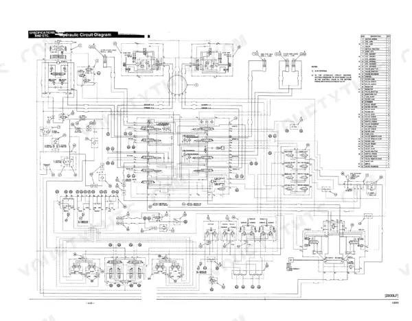
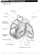
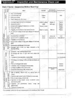
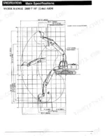
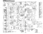
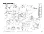
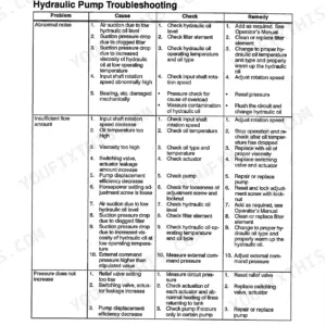
Book WDL2001-OE, the 188-page Link-Belt 2800, 3400 operator manual PDF, takes both hydraulic excavators from pre-start walkaround through travel, transport and storage. Electric and hydraulic circuit diagrams sit in the specifications chapter, so you can trace a dead switch or a sluggish function back through the system. Inspection and maintenance runs to more than a quarter of the book: the check list, the lubrication and element chart, swing and travel unit service, track shoe bolt torque and a troubleshooting section. The operation chapter maps every console switch, monitor lamp and lever. Change the fuel filter element every 500 hours and the pilot, return and drain filters every 1,000; main relief should read 4550 ± 70 PSI standard and 4980 ± 70 PSI in power up. Every hour your excavator sits parked is an hour the crew can't bill. Bookmarks jump to each chapter, and the pages print clean enough to take to the bench and get greasy.
What's Inside This Operator Manual
| System | Pages | Key Topics |
|---|
| Preface | 3 | Hydraulic Excavator, Technical Design, Operating Methods, Maintenance Procedures, Safety Information |
| Caution | 4-8 | Construction Equipment, Operator Training, Machine Maintenance, Safety Labels, Accident Prevention |
| Safety | 9-24 | Warning Signs and Labels, Before Moving to the Job Site, Operation Practices, During Operations, During Traveling, On Completion of Daily Operations, During Transportation |
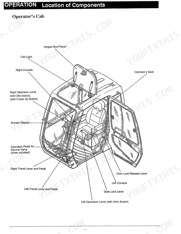
| Operation | 25-52 | Location of Components (Overall View, Operator's Cab, Instruments and Controls) |
| Operating Instructions | 53-88 | Bucket Turning Over and Replacement, On Completion of Daily Operations, Operating in Cold Climates, Operation Under Special Conditions, Special Attachments, Transportation, Storage |
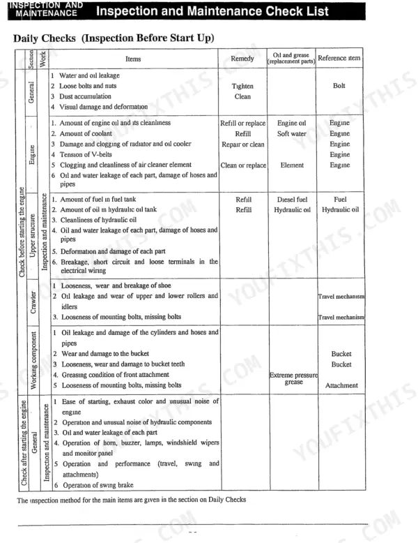
| Inspection and Maintenance | 89-140 | Precautions During Inspection, Maintenance, Rules for Inspection, Maintenance Check List, Lubrication and Element Chart, Inspection Before Starting |
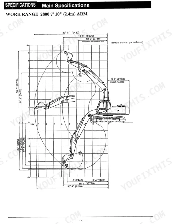
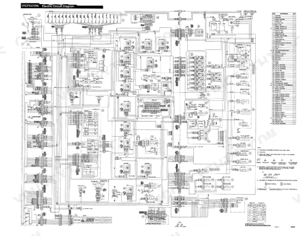
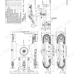
| Specifications and Etc | 141-188 | Main Specifications, Optional Parts, Electric Circuit Diagram, Hydraulic Circuit Diagram, Pressure Measurement and Adjustment, Long Front Attachment |
Quick Reference Specifications
| Specification | Value | Page |
|---|
| Fuel filter element replacement time | Every 500 hours | p. 99 |
| Pilot oil filter element replacement time | Every 1000 hours | p. 99 |
| Shoe Bolt Torque | 570-650 ft-lbs | p. 113 |
| Main Relief Pressure (Standard) | 4550 ± 70 PSI (320 ± 5 kgf/cm²) | p. 186 |
| Main Relief Pressure (Power up) | 4980 ± 70 PSI (350 ± 5 kgf/cm²) | p. 186 |
| Boom Port Relief Pressure (Up) | 5550 ± 210 PSI (390 ± 15 kgf/cm²) | p. 172 |
| Boom Port Relief Pressure (Down) | 3560 ± 210 PSI (250 ± 15 kgf/cm²) | p. 172 |
| Swing Port Relief Pressure | 4410 ± 210 PSI (310 ± 15 kgf/cm²) | p. 174 |
| Pilot Relief Pressure | 585 ± 40 PSI (41 ± 3 kgf/cm²) | p. 186 |
| Engine Oil Replacement Interval | 500 hours | p. 108 |
| Fuel Filter Replacement Interval | 500 hours | p. 107 |
| Hydraulic Oil Replacement Interval | 5000 hours | p. 117 |