
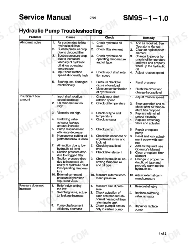
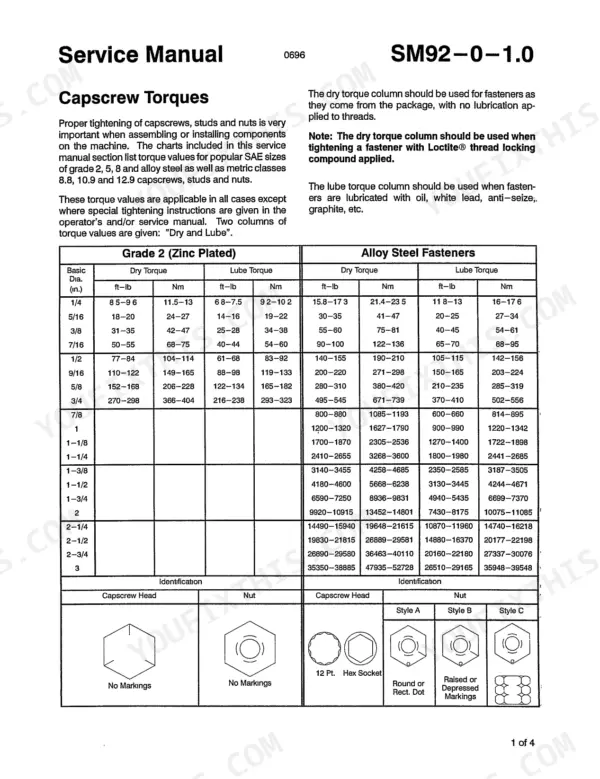
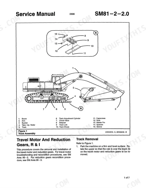
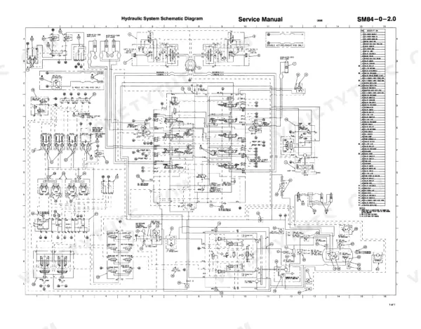
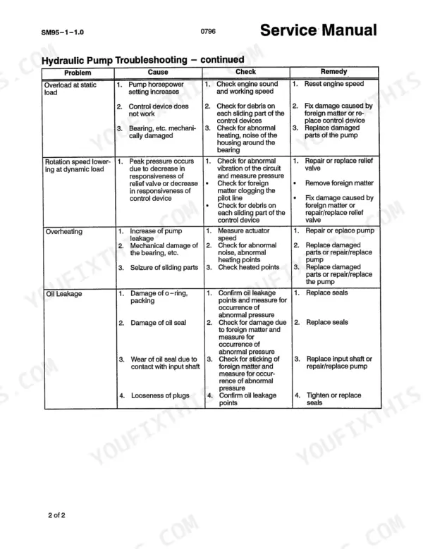
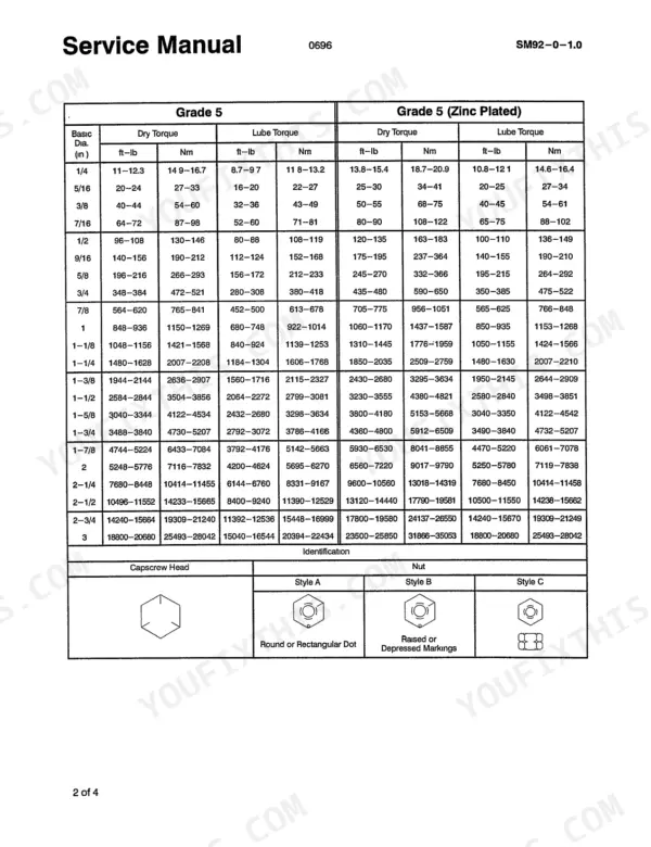
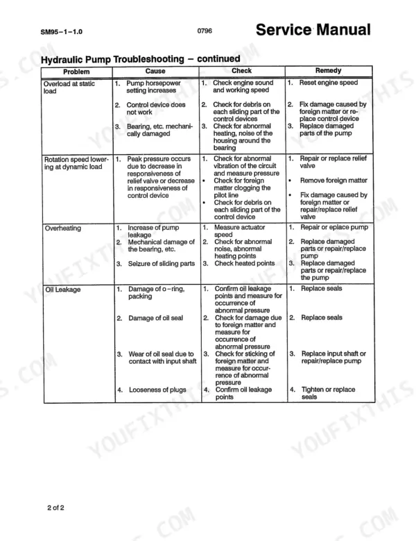
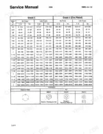
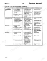
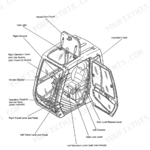
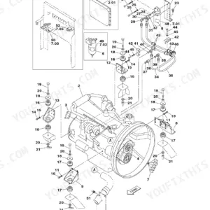
Built for the Link-Belt 5800 and 5800 Quantum hydraulic excavators, this 226-page Link-Belt 5800 service manual PDF (OEM ID 837) runs from track rollers and recoil spring to the boom, arm and bucket cylinders. Hydraulic and electrical schematics trace oil from the pump through the main control valve and rotating joint, and wiring back to the monitor system controller, while troubleshooting charts sort pump faults by symptom: abnormal noise, insufficient flow, overheating, oil leakage. Rebuild work fills more than half the book, taking the main pump, travel motor reduction gears, main control valve and hose burst check valves through teardown, inspection and reassembly. Run track shoe nuts to 557-687 ft-lb (755-932 Nm) and the pump coupling hub capscrews to 325-354 ft-lb (441-480 Nm). Every hour your 5800 sits parked is an hour the crew stands idle. Bookmarked and text-searchable, the file goes wherever you take the 5800: shop bench, service truck or jobsite trailer.
What's Inside This Manual
| System | Pages | Key Topics |
|---|---|---|
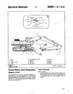
| Lower Mechanism | 3-32 | Travel Motor & Reduction Gears, R & I, Take-Up Roller, Recon, Upper Rollers |
| Upper Mechanism | 33-36 | Swing Motor and Reduction Gears |
| Engine | 37-40 | Throttle Motor |
| Hydraulic Equipment & Lines | 41-54 | Hydraulic System Schematic Diagram, Pilot Pump, R & I, Hydraulic Pump, Hydraulic System Cleaning Procedure, Rotating Joint |
| Controls | 55-64 | Joystick Control Valve, Travel/Service Control Valve, Main Control Valve |
| Attachment | 65-76 | Boom Cylinder, Arm Cylinder, Bucket Cylinder |
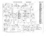
| Electric Parts | 77-84 | Electrical System Schematic Diagram, Monitor System Controller, R & I/Adjustment |
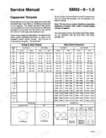
| Name Plates & Accessories | 85-90 | Capscrew Torques, Spare Pump, R & I |
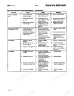
| Hydraulic Pump Troubleshooting | 91-92 | Abnormal Noise, Insufficient Flow, Pressure Increase, Overheating, Oil Leakage |
| Spare Pump Recondition | 93-102 | Disassembly, Cleaning and Inspection, Assembly, Troubleshooting Chart |
| Pilot Pump Recondition | 103-106 | Disassembly, Cleaning and Inspection, Assembly, Shaft Seal Replacement |
| Hydraulic Pump Recondition | 107-134 | Disassembly, Control Section Disassembly, Directional Control Valve Removal, Assembly, Regulator Cover Assembly |
| Travel Motor Recondition | 135-148 | Disassembly, Brake Valve, Relief Valves, Speed Control Valve, Troubleshooting |
| Travel Motor Reduction Gears Recondition | 149-170 | Disassembly, Subassemblies, Cleaning and Inspection, Assembly |
| Main Control Valve Recondition | 171-190 | Disassembly, Pilot Valve, Spool Sections, Anti-Drift Valves, Assembly |
| Cylinder Recondition (Boom, Arm, Bucket) | 191-226 | Boom Cylinder, Arm Cylinder, Bucket Cylinder, Hose Burst Check Valve, Cushion Valve, Stack Valve |
Quick Reference Specifications
| Specification | Value | Page |
|---|---|---|
| Locknut (36) torque | 26-32 ft-lb (36-42 Nm) | p. 138 |
| Plugs (19,23,25) torque | 64-72 ft-lb (86-98 Nm) | p. 140 |
| Capscrews (36) torque | 289-326 ft-lb (392-442 Nm) | p. 153 |
| Track shoe nut torque | 557-687 ft-lb (755-932 Nm) | p. 11 |
| Pilot pump capscrew torque | 21-26 ft-lb (28-35 Nm) | p. 43 |
| Hydraulic pump capscrew torque | 50-55 ft-lb (65-75 Nm) | p. 48 |
| Coupling hub wedges and capscrews torque | 325-354 ft-lb (441-480 Nm) | p. 47 |
| Boom cylinder weight | 855 lb (388 kg) | p. 66 |
| Boom cylinder rod mounting eye clearance | 0.059 to 0.118 in (1.5 to 3 mm) | p. 67 |
| Filter torque | 22-28 ft-lb (30-38 Nm) | p. 129 |
| Capscrews (4) torque | 130-152 ft-lb (176-206 Nm) | p. 153 |
| Swing cushion valve plug (9,22) torque | 12 ft-lb (15 Nm) | p. 160 |


