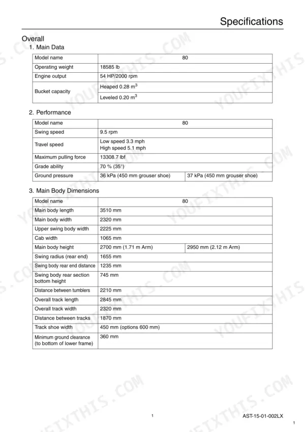
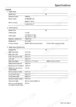
| Specifications | 19-23 | Main Data, Performance, Main Body Dimensions, Engine, Cooling System, Upper Side Work System, Operating Device, Swing Units |
| Hydraulic Equipment | 24 | Hydraulic Device, Control Valve, Cylinder |
| Capacities, Filters | 25-26 | Coolant and Oil Capacities, Hydraulic Oil Filters, Fuel Filter |
| Overall View | 27-28 | Standard Arm, Long Arm |
| Work Range Diagram | 29-30 | Work Range Diagram (80), Standard Arm, Long Arm |
| Optional Components | 31-32 | List of Optional Components |
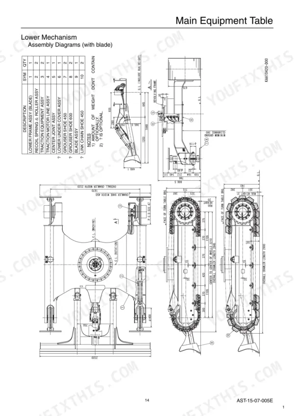
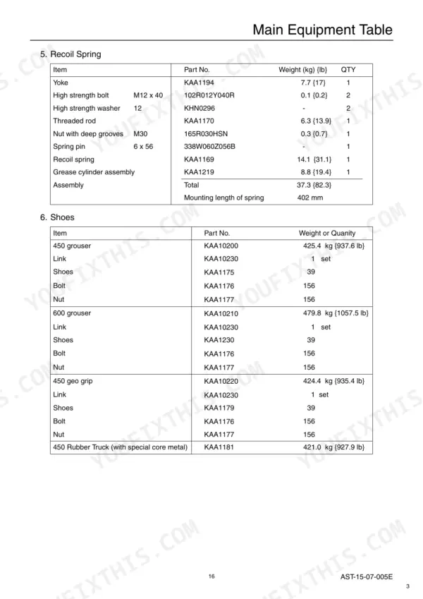
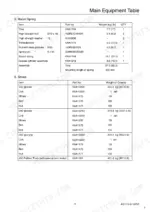
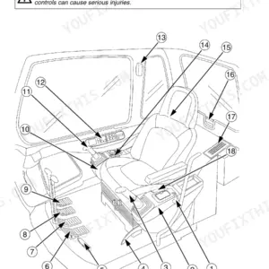
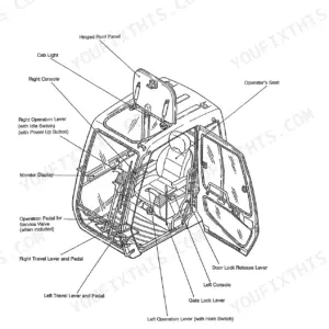
| Equipment Configuration and Main Equipment Table | 33-53 | Overall Configuration, Operator's Cab, Lower Mechanism, Travel Unit, Rollers, Recoil Spring, Shoes |
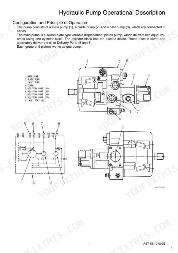
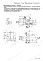
| Hydraulic Pump and Control Valve Operation | 54-86 | Hydraulic Pump Operation, Flow Control, Control Valve Operation, Relief Valves, Swing Motor |
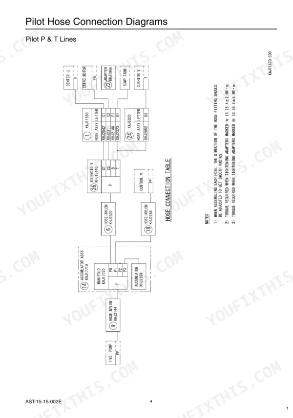
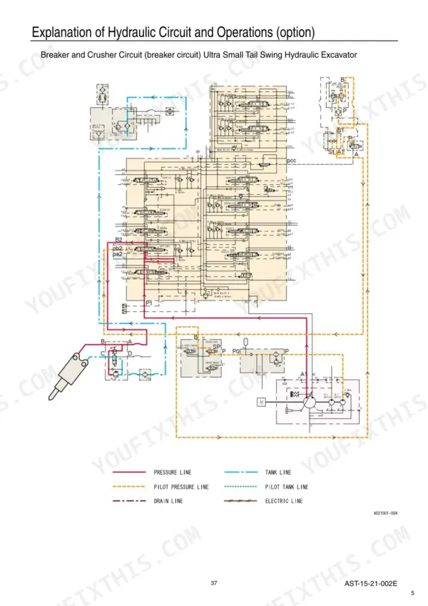
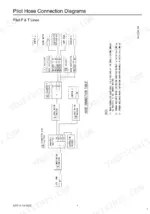
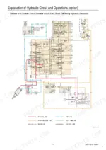
| Hydraulic Circuit Section | 87-148 | Port Locations, Pilot Hose Connection, Travel Circuits, Swing Circuit, Bucket Circuit, Boom Circuit, Backup Circuits |
| Electric Circuits Section | 149-184 | Monitor Display, Engine Control, Electric Circuit Diagrams, Harness Diagrams, Wiring Diagrams |
| Measuring / Adjusting Pressure | 185-210 | Measuring Pressure, Adjusting Pressure, Attachment Dimensions, Appendix, Compatibility, Disassembling and Maintenance Instructions |
| Safety | 211-294 | Precautions for Use, Numerical Conversion Table, Main Equipment Table, Fuel / Lubricants and Filters, Main Body Weight, Lifting Capacity |
| Lower Mechanism | 295-378 | Upper Mechanism, Attachments, Take-Up Roller, Rotating Joint, Air Conditioner |
| Maintenance Standards | 379-410 | Check Sheet, Drive Sprocket, Track Shoe, Inspection Gauge |
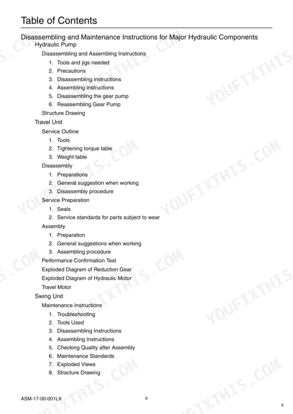
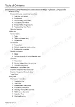
| Hydraulic Pump | 411-438 | Disassembling and Assembling Instructions, Disassembling Instructions, Assembling Instructions, Disassembling the Gear Pump, Structure Drawing |
| Travel Unit | 439-484 | Service Outline, Disassembly, Assembly, Performance Confirmation Test, Exploded Diagram of Reduction Gear |
| Swing Unit | 485-530 | Maintenance Instructions, Troubleshooting, Tools Used, Checking Quality After Assembly, Exploded Views, Anti-Reverse Valve |
| Control Valve | 531-558 | Maintenance Instructions, Cleaning, Inspection, Relief Valves, List of Control Valve Specifications |
| Cylinder | 559-612 | Maintenance Instructions, Description of Functions, Error Diagnosis, Storage Standards, Special Jigs for Repair |
| Remote Control Valve | 613-656 | Solenoid Valve (3 Stack), Cushion Valve |
| Spin Ace Tier III Shop Manual | 657-756 | Fuel / Lubricants and Filters, Main Body Weight, Maintenance Standards |