

A travel motor that creeps on one side, or a swing brake that will not release, gets diagnosed a lot faster with the Link-Belt 135 shop manual PDF open: 760 pages of factory service data for the 135 hydraulic excavator, issued under OEM ID MSM-17-00-001LX. Hydraulic schematics trace the pilot circuits for travel, swing, arm, and boom port by port, while wiring and harness diagrams map the monitor and engine control electronics. Over a third of the book walks through disassembly and maintenance of the major hydraulic components, main pump through regulator. Set the pump to its 4970 psi operating pressure and check travel relief against the 5410 psi setting before you condemn anything downstream. Guess wrong there and you buy the part twice and do the teardown twice. Bookmarked and text-searchable, this PDF goes wherever your machine is working.
What's Inside This Link-Belt 135 Manual
| System | Pages | Key Topics |
|---|---|---|
| Specifications | 19-42 | Main Data |
| Major Equipment Specifications | 43-66 | Equipment Configuration (Overall, Operator's Cab, Lower Mechanism, Lower Assembly Diagram Overall, Lower Assembly Diagram Overall with Dozer Blade) |
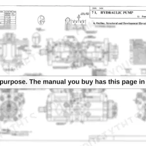
| Hydraulic Section | 67-120 | Hydraulic Pump Operational Description (Structure and Operation Principle, Attached Drawing 1, Pump Development Diagram, Attached Drawing 2, Pump Structure Drawing) |
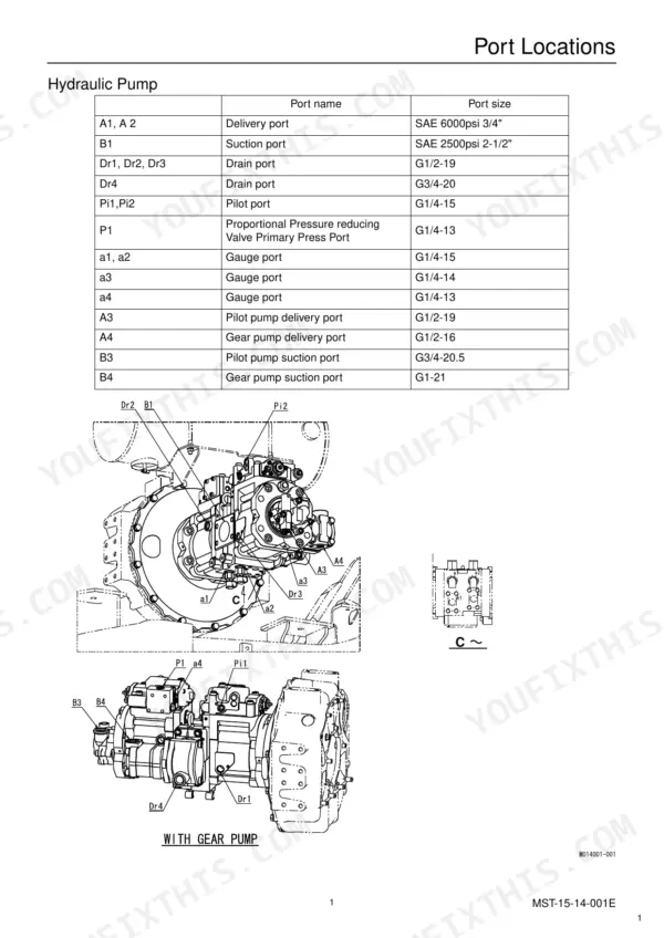
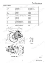
| Hydraulic Circuit Section | 121-162 | Port Locations, Pilot Hose Connection Diagrams, Functional Description, Travel Circuits, Swing Circuits, Arm Circuits, Boom Circuits, Option Circuits |
| Electric Circuits Section | 163-198 | Wiring Diagrams, Harness Diagrams, Operational Description (Monitor Display, Engine Control, Monitor Output Control, Monitor Display Control) |
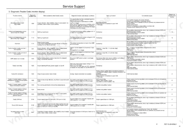
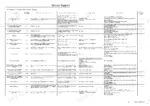
| Service Support | 199-260 | Screen Operations, Screen Display List, Screen Display Details, Trouble Display, Main Equipment Structural Diagrams |
| Maintenance Section | 261-282 | Measuring Adjusting Pressure, Pressure Adjustment, Compatibility, Attachment Installation Methods |
| About This Shop Manual | 283-334 | Safety, Introduction, Using Technical Information, Tightening Torque, Numerical Conversion Table |
| Fuel / Lubricants and Filters | 335-344 | Fuel / Lubricants for Different Ambient Temperature Settings, Engine Fuel and Maintenance of Fuel Filters |
| Performances | 345-354 | Lifting Capacity |
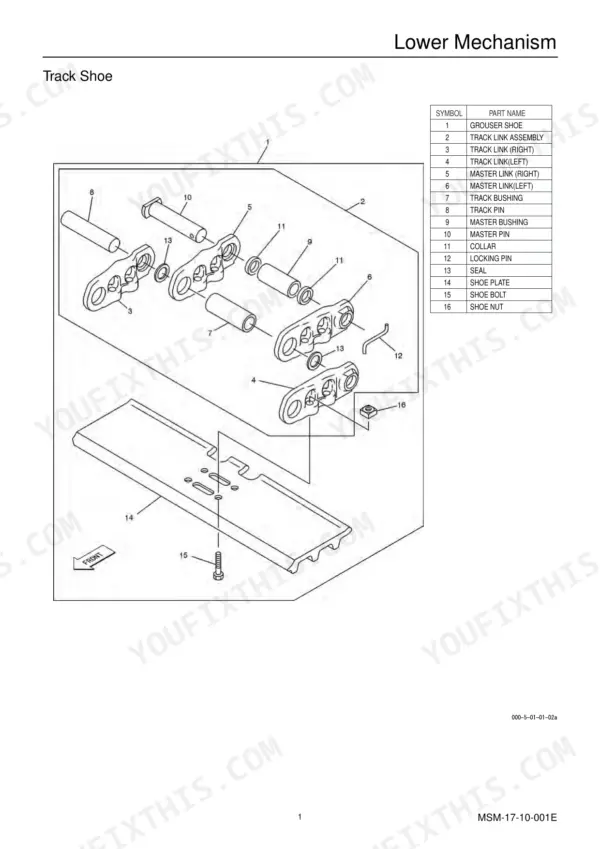
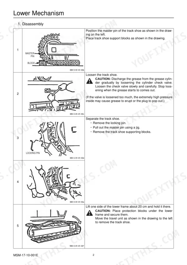
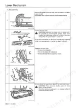
| Disassembling and Maintenance Instructions for Main Body | 355-390 | Maintenance Instructions, Lower Mechanism, Travel Unit |
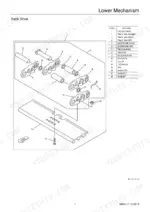
| Disassembling and Maintenance Instructions for Major Parts | 391-478 | Attachments, Take-Up Roller, Upper Roller |
| Disassembling and Maintenance Instructions for Major Hydraulic Components | 479-760 | Hydraulic Pump Maintenance, Regulator Handling, Regulator Maintenance |
Quick Reference Specifications
| Specification | Value | Page |
|---|---|---|
| Oil cooler capacity | 28.6 kW | p. 20 |
| Main pump operating pressure | 4970 psi | p. 50 |
| Travel unit operating pressure | 4970 psi | p. 47 |
| Travel unit relief valve set pressure | 5410 psi | p. 47 |
| Oil cooler weight | 29.8 lb | p. 51 |
| Lower-roller weight | 47.2 lb | p. 313 |
| Shoe bolt tightening torque | 267 - 312 Nm | p. 357 |
| Drive sprocket tightening torque | 267 - 312 Nm | p. 357 |
| Upper roller (carrier roller) tightening torque | 267 - 312 Nm | p. 357 |
| Link pitch (h) standard value | 171.45 mm | p. 23 |
| Clearance between the piston and cylinder bore (D-d) (K3V63/K5V80) | 0.028/0.056 mm | p. 489 |
| Operating weight | 29750 lb | p. 19 |
Link-Belt 135 Common Problems This Manual Covers
Link-Belt 135 final drive weak on one side, machine pulls and track barely turns
Check travel circuit relief pressure first; the travel relief valve is set at 5410 psi. If pressure holds but the track still drags, pull the travel motor and inspect the parking brake friction plates, which must hold 206 N·m braking torque per page 550.
Manual Section: Disassembling and Maintenance Instructions for Major Hydraulic Components p. 550All functions slow and weak, cycle times drag once the hydraulic oil warms up
Test main relief pressure at the pump; spec is 4874 psi, listed on page 24. If relief checks out but flow is still down, tear down the main pump and measure piston-to-bore clearance against the 0.028/0.056 mm standard on page 489. Replace the rotating group when clearance exceeds the service limit.
Manual Section: Disassembling and Maintenance Instructions for Major Hydraulic Components p. 489Boom drifts down under load and cylinder rod shows oil film after digging
Confirm drift stops with the hoses blocked off at the boom cylinder; if it does, the control valve is passing oil, not the seals. Test the overload relief valve, which should hold 5482 psi per page 24. If the rod weeps oil, replace the seal kit and inspect the rod for scoring. The control valve troubleshooting table starts on page 615, and cylinder inspection follows on page 642.
Manual Section: Cylinder Error Diagnosis p. 615Track keeps jumping the front idler and undercarriage clatters when traveling over uneven ground
Measure track link pitch against the 171.45 mm standard on page 23; a stretched chain derails no matter how tight you tension it. Check roller tread wear against the 130 mm standard dimension on page 448, then retorque shoe bolts to 267-312 Nm per page 357 before sending the machine back out.
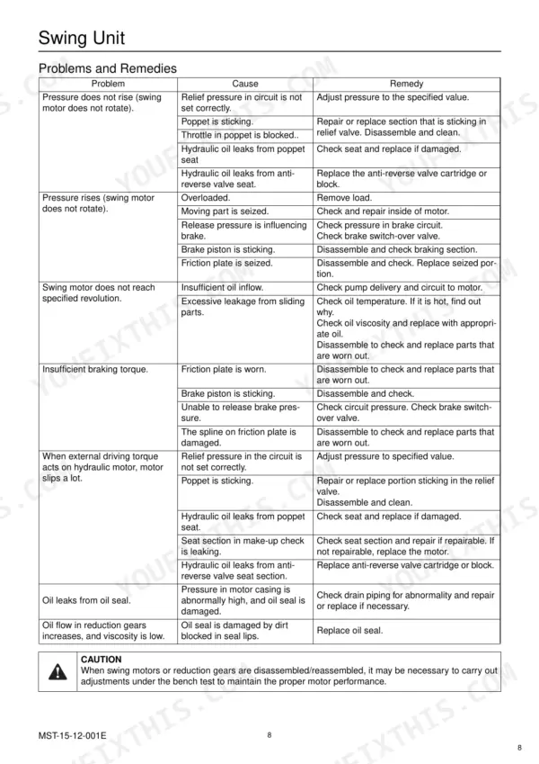
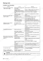
Manual Section: Disassembling and Maintenance Instructions for Major Parts p. 448Swing is sluggish, will not hold position on a slope, motor slips under load
Run the swing troubleshooting procedure starting; it covers pressure rise, insufficient revolution, and braking torque in order. Verify full-throttle swing speed reaches the 10.0 rpm spec listed on page 19. If pressure is normal but the motor still slips, pull the swing motor and inspect the rotating group. Swing unit troubleshooting starts on page 574.
Manual Section: Swing Unit Troubleshooting p. 574Frequently Asked Questions
What is the meaning of the Link-Belt 135 error code 0087?
Error code 0087 indicates a potential fuel leak or pump pressure issue. The diagnostic trouble code display condition is an actual rail pressure of 2900 psi or lower for 3 seconds or longer, which may cause engine vibration, idle instability, or a drop in output power. p. 241
How can I reset the trouble log on a Link-Belt 135 excavator?
To reset the trouble log, open the DIAG (trouble diagnosis) screen. Once there, hold down the washer switch and the light switch simultaneously for 10 seconds to reset the log. p. 215
What are the replacement specifications for the hydraulic main pump on the 135?
The main pump is a double variable displacement piston pump. The set pressure for the main relief valve is 4874 psi for the boom, arm, and bucket, and 4061 psi for the swing. p. 24
What is the tightening torque for the main relief valve on the Link-Belt 135 control valve?
Torque spec for the main relief valve on the control valve comes in at 78 to 88 N·m, and the locknut on that same valve takes 27 to 31 N·m. p. 613
What is the capacity of the hydraulic oil tank for the 135?
The hydraulic oil tank capacity is 125 liters (33 gallons), with a hydraulic oil regulation amount of 21.3 gallons. p. 65
Is this Link-Belt 135 manual a PDF I download?
You download the Shop Manual yourself: 760 pages, searchable PDF, available immediately. Keep a copy on every device you use.
Can I print this Link-Belt 135 manual?
Yes. The PDF has no DRM restrictions, so print any page or section you need for your shop. Works with any standard printer.


Reviews
There are no reviews yet.